Like many Music From Outer Space projects, the Alien Screamer was designed to be easy to build and to help learn the basics of electronic synthesis and DIY electronics along the way. With our recent updates to the Alien Screamer project, you can choose from three main configurations depending on your level of DIY experience with electronics, case-building and/or panel-making:
- Basic Kit—includes the PCB and electronic parts required to build the project. You’ll need to create your own panel and case to display and house the project.
- Basic Kit + Panel—includes the PCB, Aluminum Panel and electronic parts required to build the project. You’ll need to create your own case (enclosure)
- Full Kit—includes the PCB, Aluminum Panel and Case. The case also includes a second speaker, speaker grilles, PCB and panel mounting hardware, and a DC power jack so you can plug in a wall-wart power supply (optional) in addition to the battery.
Article by Ray Wilson
Features

|
|
Table of Contents
- Introduction
- Schematic Page 1
- PC Board Designators and Values
- Bypass Amplifier When Jack Inserted
- Panel Layout and Wiring
- Parts List (BOM)
- Parts Kit Notes
- Tips for MFOS 3D Printed Enclosure

Introduction
There's no time like the present to start that hobby you've wanted to get going for years. This is a great project for beginning your synth-diy journey or if you're already building sound gear this is a great project to make for that imaginative young person in your life. It's a great introduction to synth-diy (the oscillator is a ramp core driven by an exponential V to I convertor). Don't expect to play this as a traditional instrument (although it does a decent imitation of a theremin in the right hands) but do expect to have a lot of creative, imaginative sound making fun. From star trek communicators to birds tweeting you'll find a wealth of coolness.
There is a nice kludge area on the PC board for adding your personal electronic touch to the circuit. If you come up with a cool mod and would like to share it with the diy community send it in and I'll post it with credit to you.
Schematic Page 1
View as PDF Table of ContentsThe MFOS Alien Screamer circuit consists of three main components: a voltage controlled oscillator, a low frequency oscillator and a one watt amplifier that drives a small speaker. The unit is powered by one nine volt battery and due to the low current drain of the LM324 it gets a lot of miles out of a nine volt battery. The circuit draws about 10mA. Battery B1 is switched into the circuit by S4 (SPST toggle switch). Capacitor C8 (470 uF) is the main supply filtering cap. It holds a good bit of charge which supplements the battery when the unit draws additional current. R22 and R23 (4.7K resistors) form a voltage divider that supplies a voltage level which is halfway between the battery's plus and minus terminals. This voltage is used as a ground reference in the circuitry. C9 and C11 (.1uF ceramic capacitors) are placed very close to the power pins of the LM324 to stabilize it's operation and filter power supply transisent noise from polluting the op amp's bias network.
The VCO which is the main sound generating component in the unit works as follows. U1-D and associated components comprise a linear voltage to exponential current convertor which gives the VCO a very wide frequency range. As the voltage on the base of Q2 (NPN 2N3904) changes linearly current into the collector of Q3 (NPN 2N3904) changes exponentially. So as Q2 base voltage changes by 18mV the current into Q3's collector changes by a factor of about two. Assuming that the lowest current possible into Q3's collector is .5uA you can see that as we go from 230mV to 0mV we cover about 12 steps of 18mV which causes the current to ideally double 12 times along the way (.5uA, 1ua, 2ua, 4ua, 8ua, 16ua, 32ua, 64ua, 128ua, 256ua, 512ua, 1024ua). Since the oscillator's frequency is linearly related to this current, doubling the current double's the frequency. Thus we get a nice wide range of frequency change as we modulate the voltage going to the exponential current convertor of from a few ticks a second to 8 or 10 KHz.
The second important part of the VCO is the ramp generator and comparator. U1-A (1/4 LM324 Quad Low Power Op Amp) and associated components comprise a resettable integrator (ramp generator). Initially the output of U1-B (used as a comparator) is at negative saturation (near battery negative in our case) which reverse biases D1. In this condition the gate of N-Channel JFET Q1 is held at battery negative through 2M resistor R2. Under this condition the source and drain of Q1 are electrically isolated from one another as if the transistor wasn't even there. Now as current flows into the collector of Q3 the output of U1-A begins to ramp up (from the ground reference level). The rate at which U1-A's output ramps up is directly proportional to the magnitude of the current flowing into the collector of Q3. More current faster ramp, less current slower ramp. U1-B is used as a comparator in the circuit. A comparator compares the voltage on it's inverting input (- symbol) to the voltage on it's non-inverting input (+ symbol) and when the voltage on the non-inverting input is above the voltage on the inverting input the output goes high (to near battery positive). When the voltage on the non-inverting input is below the voltage on the inverting input the output goes low (to near battery negative).
In the case of U1-B the voltage on the inverting input is fixed and set by a voltage divider made up of R17 (10K resistor connected to BP) and R20 (15K resistor connected to BN) and is approximately 5.4V related to BN and about .9V related to ground (junction of R22 and R23). The integrator U1-A ramps up from the ground level and when it gets just above .9V above ground (5.4V above battery negative) the output of comparator U1-B goes high as fast as the output can get there. When U1-B's output goes high D1 is forward biased and the gate of Q1 is brought high via current limiting 10K resistor R3. When the gate of an N-Channel JFET is brought high it is like the source and drain are shorted together. The result of this is that the voltage across C3 is neutralized and the output of U1-A immediately falls to ground level. When the ramp is reset by turning on Q1 the output of U1-A goes to ground level which is below the voltage level on the inverting input and U1-B's output goes low (as fast as it can) allowing U1-A to ramp up again. This action results in ramp wave oscillation at the output of U1-A the frequency of which is directly dependent on the current flowing into Q3's collector. As we saw from above we can modulate that current quite a bit and thus cause the VCO to oscillate over a nice wide range.
Two sources of "control voltage" are fed to the exponential convertor. One comes from the wiper of the VCO Frequency pot (R13 100K linear pot). Since the battery voltage is applied across the pot the wiper picks off from 9V to 0V as it is turned clockwise. That voltage is applied to the base of Q2 after being attenuated via the voltage divider made up of R10 (75K resistor) and R14 (2K resistor). Since R14 is connected to the "ground" point (the reference voltage at the junction of R22 and R23) the base of Q2 sees about from -116mV to about +116mV (referenced to the ground point). When the voltage is low the frequency is high and when the voltage is high the frequency is low. This is somewhat counterintuitive and usually the controlling voltage is applied to the base of Q2 via an inverting op amp which corrects this seeming anomaly. However since we are only interested in making some cool sounds we just make the pot work the way we want and so as you turn it clockwise (toward 0V) the frequency goes up and as you turn it counter-clockwise (toward 9V) the frequency goes down.
The other source of VCO "control voltage" as it is called comes from the LFO. The LFO is a much simpler type of oscillator and again uses the principles of the comparator to operate. In this oscillator we bias the non-inverting input with 100K resistors R11, R18 and R19. Without R19 in the circuit the voltage at the junction of R11 and R18 would be about 4.5V (referenced to battery negative). However the output of U1-C fed to this junction via R19 100K resistor influences the voltage. When U1-C's output is high (near battery positive) the voltage at the junction of R11, R18 and R19 goes higher than ground (about 1.5V referenced to ground) and if U1-C's output is low (near battery negative) the voltage at the junction of R11, R18 and R19 goes lower than ground (about -1.5V referenced to ground). Consider that the output of U1-C is low. In this condition the voltage on the non-inverting input is below ground, however the low level at the output is also pulling current through R5 (1M LFO Rate pot) in series with R4 (3K resistor) causing the voltage level on C2 to go down. Eventually the voltage on C2 which is connected to the inverting input will be lower than the voltage on the non-inverting input (junction of R11, R18 and R19) and the comparator's output will pop high. Now the bias on the non-inverting input is above ground and C2 begins to charge via R5 and R4 until it gets to a level above the voltage on the non-inverting input and whammo U1-C's output will shoot low. This process repeats resulting in square wave oscillation on the output of U1-C. LFO Rate pot R5 controls the frequency of oscillation by controlling the rate at which C2 charges or discharges. R4 3K resistor is there to limit the current flowing in and out of C2 to what an op amp can reasonably handle. The rate can be changed over a nice wide range (not as wide as the VCO but from a few hertz to a few hundred hertz).
While square wave modulation can be interesting adding some shaping to the output of U1-C adds variety to the modulation waveforms fed to the VCO. S2 is used to select between either a low pass filtered version of the square wave R12 (75K resistor) and C5 (1uF electrolytic cap) do the shaping or a choice of the output of U1-C (square wave) or a differentiated version of the square wave (the square wave delivered through C4). The differentiated wave is interesting because only the edges of the square wave (and rapid discharge tails) get through. I find that the differentiated waveform makes awesome bird tweet sounds. S1 and S2 allow selection of the LFO waveforms. The common pole of S2 is connected to one end of the LFO Mod Depth pot which controls the amount of LFO modulation the VCO sees. We pick the voltage off of the wiper of R6 (100K linear pot) and feed it to the junction of R14 and R10 via R7 100K resistor. The LFO voltage has the same effect on the VCO's frequency as the VCO Frequency pot. When the LFO's output is high the frequency of the VCO goes lower and vice versa. The output of the LFO also drives an LED via 4.7K current limiting resistor R21. Last but not least the output of the LFO is used to reset the VCO's ramp generator (when SPST toggle switch S3 is closed) to produce what is known as sync effects. The leading and trailing edges of the LFO's square waves propogate through C6 and change the bias level of the VCO's comparator. This has the effect of resetting the VCO during it' otherwise normal cycling and results in some totally cool sounds.
Finally we have our amplifier which is basically U2 an LM386N-4 1W integrated audio amplifier. We add the components that the LM386N data sheet tells us to and voila we have a complete 1W amplifier. For more on the operation and internal circuitry of the LM386N see it's data sheet (Google LM386 and you'll find a plethora of them). The output of the VCO is fed to one end of R24 which is used as a variable attenuator (volume pot) with the other side connected to battery negative. We block DC from getting to the input of the amplifier via C12 1uF non-polarized capacitor. As we advance R24 we pick off more and more VCO and if we go the other way... less and less. Resistors R25 (100K) and R26 (4.7) further attenuate the level fed to the amplifier's input from the volume pot so that we don't overdrive the amplifier's input resulting in distortion.
The junction of C12 and R25 is fed to the line out 1/4" phone jack which you can use to connect to your amplifier or mixing board. The level can be adjusted with the unit's volume control (R24).
Well that's that. Build it, connect the battery and turn the knobs and have fun making cool sounds. Put the output through effects for some extra craziness (echo, phase shifting, flanging, reverb, etc). Enjoy.
PC Board Designators
View as PDF Table of ContentsThis view is good for when you are trouble shooting. Notice the pad next to X10. It is so you can connect the two speaker wires right there. The extra unmarked pad goes to BN (battery negative).
PC Board Values
View as PDFThis view is good for when you are stuffing the PC board. Notice the pad next to X10. It is so you can connect the two speaker wires right there. The extra unmarked pad goes to BN (battery negative).

MFOS Alien Screamer 3D Printed Enclosure Assembly Details
Scroll down for modifications, details, and legacy assembly information.
Recommended changes from the standard Alien Screamer wiring described on the Alien Screamer MFOS Project Website are detailed here.
-
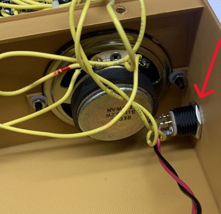
Install and tighten the nut on the Power Connector before installing the speakers. It is difficult to reach after the speakers are installed.
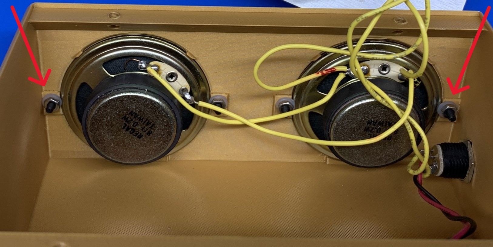
-
Install the corner speaker screws, nuts and washers and leave them loose before installing the speakers, as they are difficult to install once the speakers are in place. Then slip the speaker’s edge in place under the plastic washer.
-
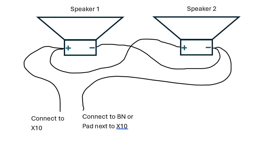
The 3D Printed Enclosure uses two speakers. The speakers should be wired in parallel as shown:
- It is suggested to Implement the "Switched Jack Amplifier Bypass" modification (See the Alien Screamer MFOS Project Website) from the standard Alien Screamer wiring described on the MFOS website. This modification silences the speakers on the enclosure when a cable is plugged into the Audio Output jack. (R25 is relocated, and the X8 and BYPASS Pads are used).
- If you’d prefer the unit to be louder when sounding from the speakers, the following modification may be implemented. This modification will increase current draw and thus greatly reduce the expected operating time from a battery. (NOTE: this modification increases the volume to a level that works well with the synthCube/MFOS 3D Printed Enclosure and its speakers. The Amplifier Gain Boost Option shown in the Alien Screamer MFOS Project website increases the volume and power draw much more than this modification does.)
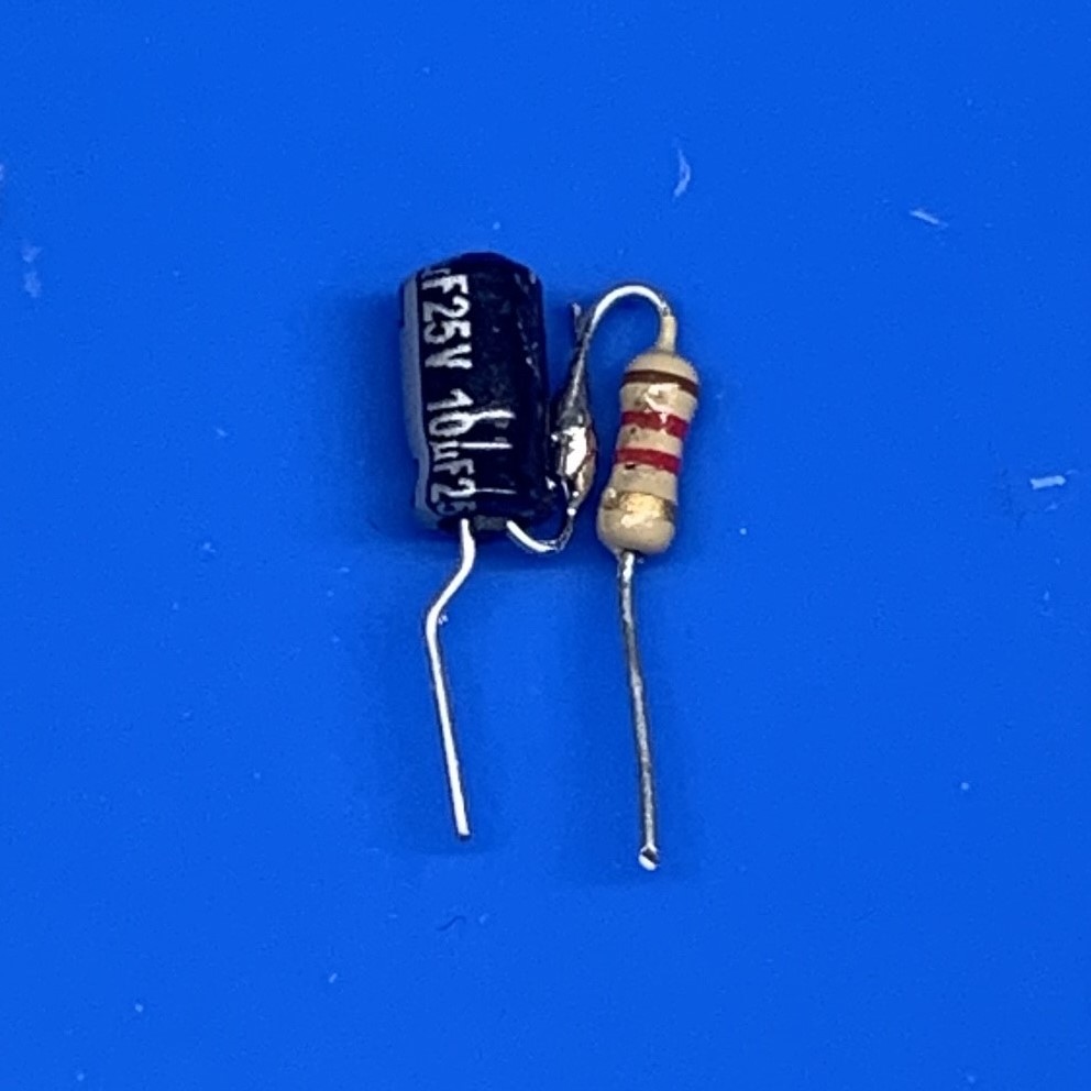
Prepare the leads of a 10uF 25V minimum electrolytic capacitor and 1.2 kOhm resistor and solder them together as shown. The goal is to create a single "combination component" from these two parts that may then be installed into the PC board. The positive pin of the capacitor connects to the resistor. (NOTE:Usually the positive side is not marked, instead the negative side of the capacitor is marked with a (-) sign or stripe.)
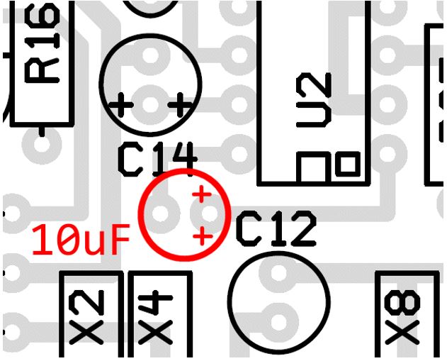
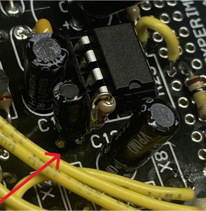
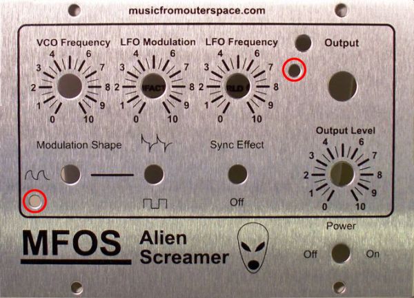
Install this "combination component" into the "10 uF" location on the PC board near C12 and C14 as shown. The location is red in the image below. The resistor lead should connect to the + side pad as indicated in the silkscreen.
The installed "combination component" should look as shown below when installation is complete.
-
To install the LED to the panel using the bezel included in the enclosure kit, first install the bezel from the front of the panel, pushing it until it snaps into place.
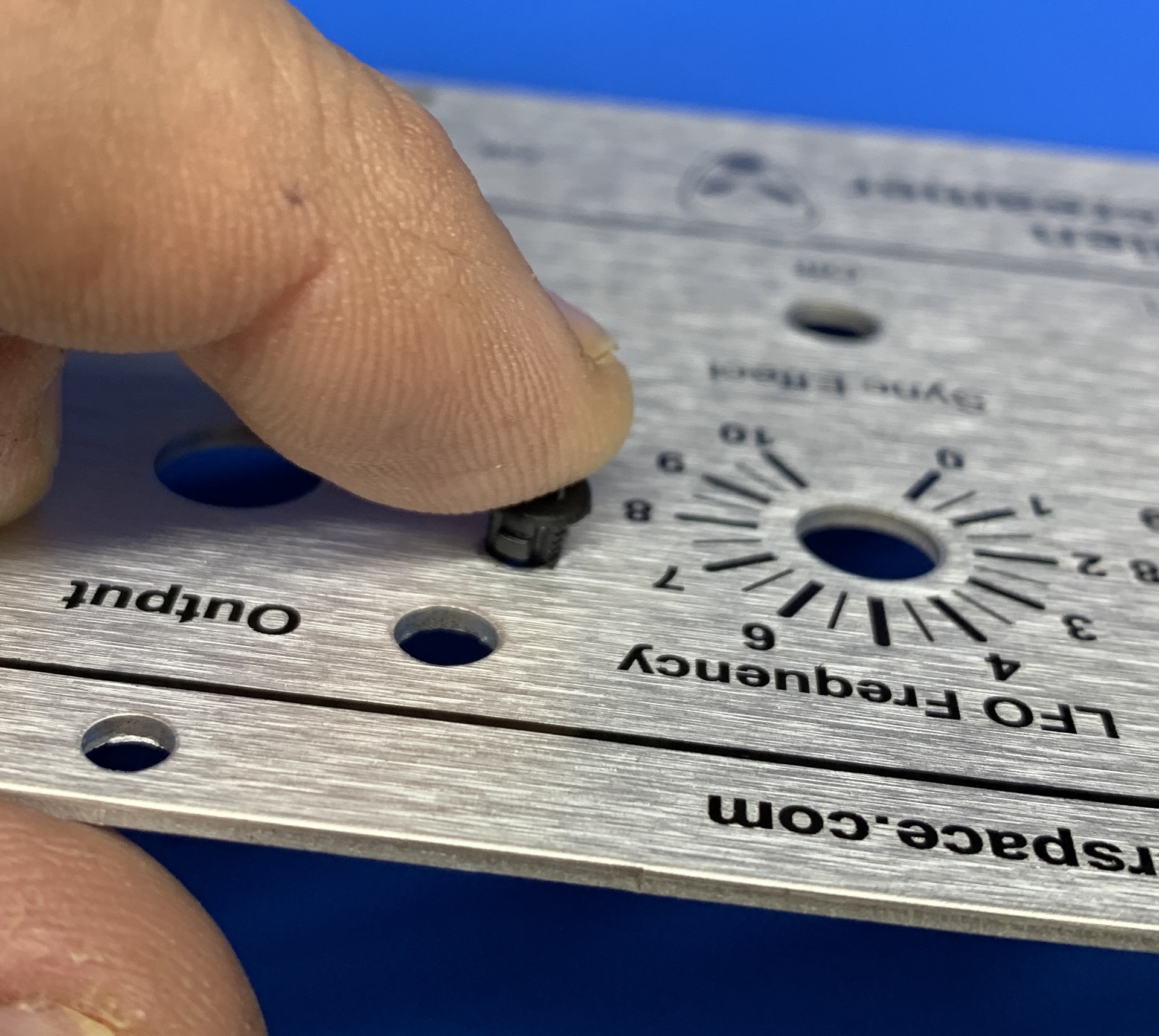
Next, while holding the bezel in place with one finger on the front of the panel, push the LED into the bezel from the rear of the panel.
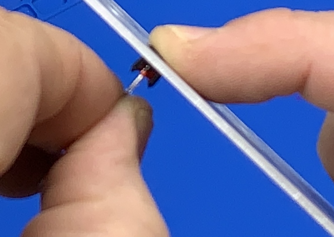
Note: The longer lead of the LED is the Anode, which connects to X7 on the Alien Screamer PCB. The other LED lead, the Cathode or (Kathode) connects to BN on the Alien Screamer PCB. Heat shrink tubing or electrical tape is recommended to avoid short-circuiting the two leads of the LED when connecting the wires.
-
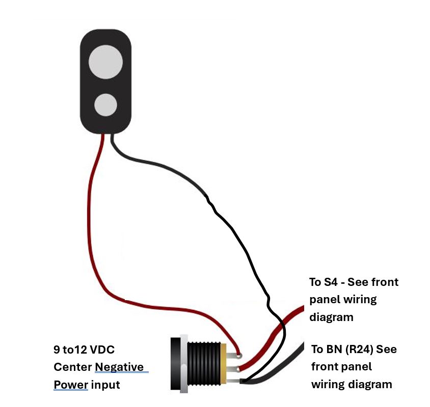
Suggested Power and battery wiring are shown below. This arrangement disconnects the internal battery when an external power supply is used. The synthCube/MFOS 3D Printed Enclosure uses a 9 to 12 VDC Center Negative power supply. This is the type used for most guitar effects pedals. NOTE: The front panel wiring diagram is available at the Alien Screamer MFOS Project website.
- Be careful to not overtighten four self-threading screws that hold the front panel to the 3D printed enclosure. Stop turning them almost as soon as they “bottom out” on the front of the metal panel. The enclosure material is quite strong, but it is plastic.
Legacy Info
Amplifier Bypass Modification
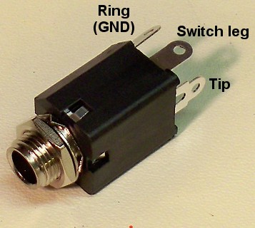
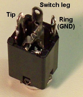
The next three images detail how to bypass the amplifier when you have a jack plugged in. You will need a jack that has a switch terminal that is connected to the tip terminal when no plug is inserted into the jack. This is the type of 1/4" jack we send in the Alien Screamer parts kit. First remove R25. If you plan to reuse it, desolder it carefully so as not to damage the leads. Solder R25 into the Kludge area as shown and then place a wire jumper from the pad connected to U3 pin 3 to the pad connected to the relocated R25. The pad on the other side of R25 is named BYPASS. Run a wire from X8 to the jack's tip connection and another wire from BYPASS to the jack's switched terminal. When a plug is not inserted into the jack points X8 (jack tip) and BYPASS (jack switch leg) are connected together and the amplifier is in the circuit. When a plug is inserted into the jack the tip terminal is disconnected from the switched terminal and the amplifier is bypassed.
This is the schematic of this change. The remainder of the schematic is the same.
Here we see the type of jack sent with the Alien Screamer parts kit with the terminals labeled.
This is the PC layout showing the relocated R25, the jumper and the points that get connected to the switched jack X8 and BYPASS.
Amplifier Gain Boost Option
You have the option to change the gain of the amplifier from it's normal 20 to an ear splitting 200 by adding a 10uF electrolytic capacitor between pins 1 and 8 of the LM386N-4 chip. Be sure to observe the polarity of the cap if you use it (positive side to goes to pin 1). There is no legend on the board for this component but I did put two pads on the PC board in case you want to use it. (see the image below). Adding the gain increasing cap causes the amplifier to draw a lot more current (about 5X more) which will eat your battery faster than you can say "DEAD BATTERY" so if you use it buy some Duracell stock first. Additionally if using the gain boosting cap I recommend you use a speaker rated for 1W since you may burn out a lower power speaker coil.
PC Board Bottom Copper
PC Board Top Copper

PC Board Silk Screen
Front Panel Wiring
View as PDF Table of Contents
This is just a suggestion but if you make your own unique panel make a corresponding wiring diagram to avoid mistakes.
IMPORTANT!!! - THIS VIEW IS LOOKING AT THE MOUNTED PANEL CONTROLS FROM THE REAR OF THE PANEL.
Front Panel Template
View as PDFThe PDF should print in actual size which is 5.5" x 4.0". Don't apply any scaling or page filling options. The two 5/32" diameter holes (one near Modulation Shape and one near LFO Frequency) are used to mount the PC board on standoffs with 1.25" long 6-32 machine screws and nuts.
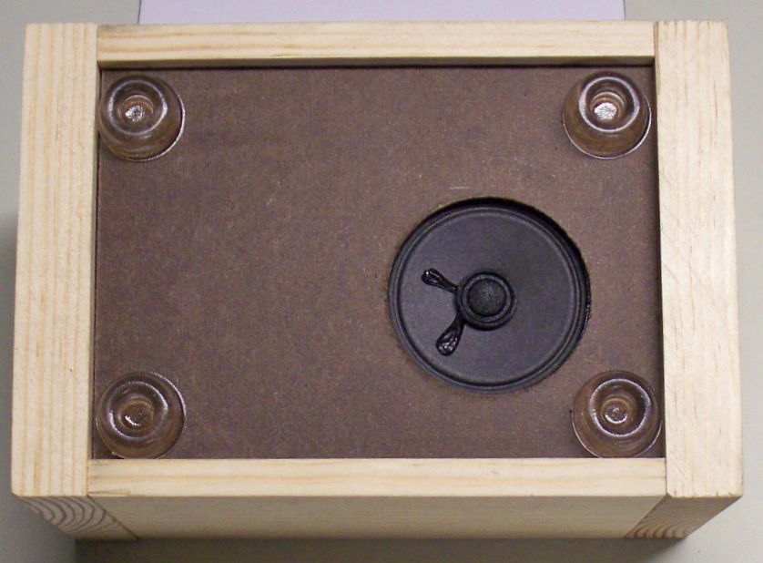
Pictures From the Prototype Build (Reference Only)
I mounted my speaker on the bottom of the case. I would recommend some screen or grill cloth to prevent curious fingers from poking a hole in your speaker. You could also drill some small grill holes instead of one large hole. I glued the case together except for the side that has the battery holder. I used a couple of screws to hold that side on so I can change the battery when necessary. Rubber feet hold the unit up so the speaker isn't blocked and the case adds some nice resonance to what would be a rather tinny sound if the speaker is just out in the air and not mounted.
 |
 |
 |
MFOS Alien Screamer Noise Box Parts List
Table of Contents... Table of Contents
All integrated circuits need to be DIP packages. When shopping for chips remember that the numbers will have suffixes like BE or BC but as long as they are DIP packages you will be fine. The suffixes typically indicate temperature ranges and package materials (plastic, ceramic, etc).
Capacitors should be rated for 16V or better.
| Qty. | Description | Value | Designators |
|---|---|---|---|
| 1 | LM324 Quad Low Power Op Amp | LM324 | U1 |
| 1 | LM386N4 (or N3) Low Voltage Audio Power Amp | LM386 | U2 |
| 1 | 2N5457 N Channel JFET | 2N5457 | Q1 |
| 2 | Transistor NPN 2N3904 | 2N3904 | Q2, Q3 |
| 1 | 1N914 High Speed Sw. Diode | 1N914 | D1 |
| 1 | General Purpose Red LED | LED | LED1 |
| 1 | Linear Taper Potentiometer | 1M | R5 |
| 3 | Linear Taper Potentiometer | 100K | R6, R13, R24 |
| 1 | Resistor 1/4 Watt 5% | 10 ohms | R27 |
| 6 | Resistor 1/4 Watt 5% | 100K | R7, R11, R18, R19, R25, R28 |
| 4 | Resistor 1/4 Watt 5% | 10K | R1, R3, R9, R17 |
| 1 | Resistor 1/4 Watt 5% | 15K | R20 |
| 1 | Resistor 1/4 Watt 5% | 220K | R15 |
| 1 | Resistor 1/4 Watt 5% | 2K | R14 |
| 2 | Resistor 1/4 Watt 5% | 2M | R2, R16 |
| 1 | Resistor 1/4 Watt 5% | 300K | R8 |
| 1 | Resistor 1/4 Watt 5% | 3K | R4 |
| 4 | Resistor 1/4 Watt 5% | 4.7K | R21, R22, R23, R26 |
| 2 | Resistor 1/4 Watt 5% | 75K | R10, R12 |
| 2 | Capacitor Aluminum Bipolar (non polarized) | 1uF | C4, C12 |
| 1 | Capacitor Ceramic | .001uF | C3 |
| 1 | Capacitor Ceramic | .01uF | C6 |
| 1 | Capacitor Ceramic | .047uF | C13 |
| 3 | Capacitor Ceramic | .1uF | C7, C9, C11 |
| 1 | Capacitor Ceramic | 100pF | C1 |
| 1 | Capacitor Electrolytic | 10uF | C14 |
| 2 | Capacitor Electrolytic | 1uF | C2, C5 |
| 1 | Capacitor Electrolytic Radial Lead 0.2" Spacing | 220uF | C10 |
| 1 | Capacitor Electrolytic Radial Lead 0.2" Spacing | 470uF | C8 |
| 1 | Speaker 2 1/4 inch 8 ohm | 8 ohm 1W | SPK1 |
| 1 | Switch SPDT Mini Toggle | SPDT | S2 |
| 3 | Switch SPST Mini Toggle | SPST | S1, S3, S4 |
| 1 | Jack 1/4" 2 Terminal | J1 | |
| 1 | Battery | 9V Battery | B1 |
| 4 | Potentiometer knobs | ||
| 1 | Battery Clip With Wires | ||
| 1 | Battery Holder | ||
| 1 | 25' Spool of Wire | ||
| 1 | 14 Pin DIP IC Socket | Highly recommended | |
| 1 | 8 Pin DIP IC Socket | Highly recommended |
Additionally you will need to construct a faceplate and case.
Alien Screamer Project Kit Notes
Table of Contents
Making a Faceplate
I have published a YouTube that demonstrates how to make a nice looking faceplate by using the faceplate PDF I provide on the site.
YouTube of How To Make Synth Front Panels Part I
YouTube of How To Make Synth Front Panels Part II
Obtaining Parts
Kits and components for your MFOS projects can be found at Small Bear Electronics and SynthCube.
The potentiometers can be rated for 1/4W and all are linear taper. All components need to have leads. Be sure you are not buying surface mount parts.
Resistor Color Chart For Resistors Used In This Project
The resistors should be carbon composition or carbon film. Use 1/4 watt resistors because 1/2 watt will be too big for the board.
Capacitor Markings For Caps Used In This Project
All capacitors should have a minimum 16V rating. There really is no maximum voltage rating but capacitors get larger as the voltage rating goes higher. I suspect that electrolytics rated at 25V, 35V or even 50V will still be small enough to fit the board. For ceramics the voltage rating can be much higher. The voltage rating is NOT CRITICAL except that ALL CAPS SHOULD BE AT A MINIMUM rated for 16V. The lead spacing for most caps on the boards from MFOS is .2" but you can always make leads with smaller (or larger) lead spacing fit so that is not a big deal.
Capacitors manufacturers have a variety of ways of marking the values on the components. When a cap is not plainly marked as .1uF (spoken as "point one microfarad") it will be marked in picofarad style. It will be marked like this: 104 which means 10 followed by 4 zeros picofarads. or 100,000 picofarads (or .1uF)
When capacitor values fall into a certain negative power of 10 they are given prefix names. Typically micro and pico with some folks occasionally using nano. So if a cap has the value of .0001 Farad we say it is 100 microfarads (or uF).
| milli | micro | nano | pico | |
| . | 000 | 000 | 000 | 000 |
If a cap has the value of .0000001 Farads we say it is .1uF (point one micro farad) but you could also say 100,000 pico farads, or 100 nano farads and be correct. You can see how the marking "104" takes up less space and space is at a premium on small parts.
So... with all that said .01 uF will be marked as 103 (10,000 pF) and 330 pico farads will be marked as 331. The next time you look at a cap I hope you are better able to tell it's value.
More examples
Switches
The switches in this circuit are switching very low currents so they do not need high voltage or current ratings. Typical miniature toggle switch ratings are 1 to 5 amps at 115VAC which is way more than they will ever see in this circuit but that's what they make. Buy the cheapest switches you can because they will work fine. Of course if your last name happens to be Gates, Buffett, or Ellison you can buy gold plated toggle switches if you like since as long as they are the correct type (SPST (SPDT will also work as SPST)) they will all work.
More information
- Tell me something about switches?
- Reading Resistor Values
- What is a capacitor and what do the numbers on the capacitor mean?
Kits come with SPDT switches which work perfectly as SPST
I send all Single Pole Double Throw Switches in kits because they also serve perfectly as SPST switches. As you can see in this image the switch has three terminals. The middle terminal is common and is connected to either of the outer terminals depending on the position of the switch bat. The terminal that is opposite of the way the switch bat leans is the terminal in contact with the middle terminal. Either outer terminal can be used.
Bipolar or Non-Polarized Caps
Don't confuse your caps. The bipolar (or non-polarized) aluminum caps look kind of like electrolytic caps except they have no + or - markings. Instead the cap is marked B.P.
Front Panel LED Mounting
To mount the LED to the front panel I trim a small piece of pre-drilled perf board with copper pads into a small rectangle. The idea is to have perf board "ears" on either side of the LED after it is soldered to the small rectangle of perf board. I then cut double sided foam tape (the stuff that sticks forever) into small squares that I apply to the perf board on both sides of the LED (on the perfboard "ears"). I use a double stack of the foam tape so that the LED sticks through the panel less (you could go three layers if you want). I then push the LED through the panel and the double stick tape holds it in place. I leave the LED leads long so I can solder to them. If you trim them prior to wiring the panel to the PCB BE SURE TO LEAVE THE ANODE LEAD LONGER THAN THE KATHODE so you can tell them apart. I usually trim them when the intra-panel wiring is done.
1/4" Phone Jack with NC Switch to Tip Contactor
This Amphenol jack (Amphenol Part# ACJM-MVS-2S) is currently shipping in kits. It can be used to bypass the amplifier when a plug is connected to the output jack as shown above in the section entitled "Switched Jack Amplifier Bypass".
 |
 |
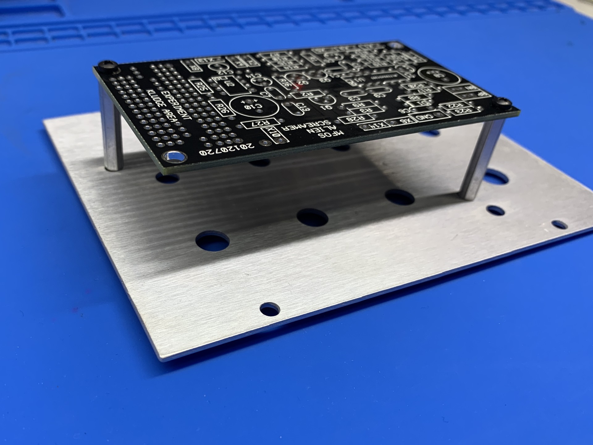
Mounting the PCB on the Alien Screamer Faceplate
Use four (4) machine screws (M2.5 x 5mm) and two (2) threaded standoffs (4.5mm od x 25mm long), as shown to mount the PC board so that it rests above the backs of the pots and switches. The components should be facing away from the panel. The screws, nuts amd spacers come with the Alien Screamer parts kit.
|
|
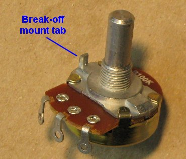
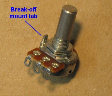
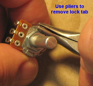
How To Remove Break-off Lock Tabs From Your Potentiometers
| If your pots have little tabs on them you will need to remove them so that you can mount them to your faceplate. It is really easy to do. Carefully snap off the little tab near the pot body and voila it's done. Some kits come with larger pots and some kits come with smaller pots. The smaller pots are at times more expensive than the larger pots. They're all good quality pots and they all work the same way. | |
Regular Sized Pots |
Smaller Sized Pots |
|---|---|
| This is the break-off lock tab which can be used to keep the pot from turning when you turn the pot shaft but tightening the mounting nut works just fine. If you have the wherewithal to drill little holes for these pesky things... be my guest. If not... read on. | |
 |
 |
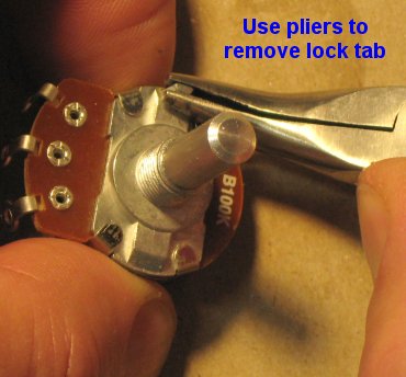
| Using pliers, grasp the tab as low on it as you can and then gently twist the pliers outward. I told you it was easy. | |
 |
 |
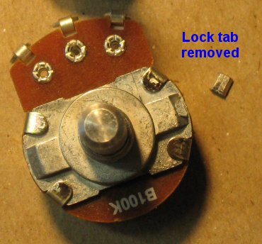
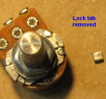
| The little broken off tabs look like this. Now you can mount your pot without the little tab getting in the way. | |
 |
 |