Ray Wilson authored this content while he was actively running MFOS as the founder and resident genius.
We retain the content because it reflects a valuable point of view representing that time and place.
Article by Ray Wilson
Introduction
I have taken a look at the VCF circuits for which I provide PCBs and have come up with some information for helping you get your filter to track 1V/octave more accurately. As with all things DIY you have to be willing to tweak, test, prod, and when necessary... poke. I hope you find this info useful and that it helps you get your filters tuned up. I am going to describe the improvements in relation to the MFOS State Variable VCF and the MFOS Low Pass VCF but please realize that many of these improvements apply to the VCF in the Sound Lab Mark II, Sound Lab ULTIMATE, and the Sound Lab ULTIMATE EXPANDER. I'm certain that a review of those schematics will reveal which components correspond to those discussed here. The linear voltage to exponential current convertors in all of these VCF circuits are virtually the same with some small variations. I feel compelled to mention that even the production version of the venerable ARP 2600 synthesizer has had minor issues that were mitigated by a component value change here and there so I think I'm in good company.Using Better Op Amps
Here is a general comment about the op amps used in the filters. Bear in mind that Analog Devices, National, Fairchild and Texas Instruments are always coming out with better lower noise, lower power op amp designs. You can substitute any of the op amps in the circuits with better lower noise versions. For example the TL08X series can be directly replased with the TL07X (or better) series amps. For best results use the lowest noise op amp you can find for input mixers. As long as the replacements work on the voltage you're using, have the same pin-out and have JFET inputs you can usually just swap out the old for the new.
State Variable VCF 1V/Octave Tracking & Range Improvements
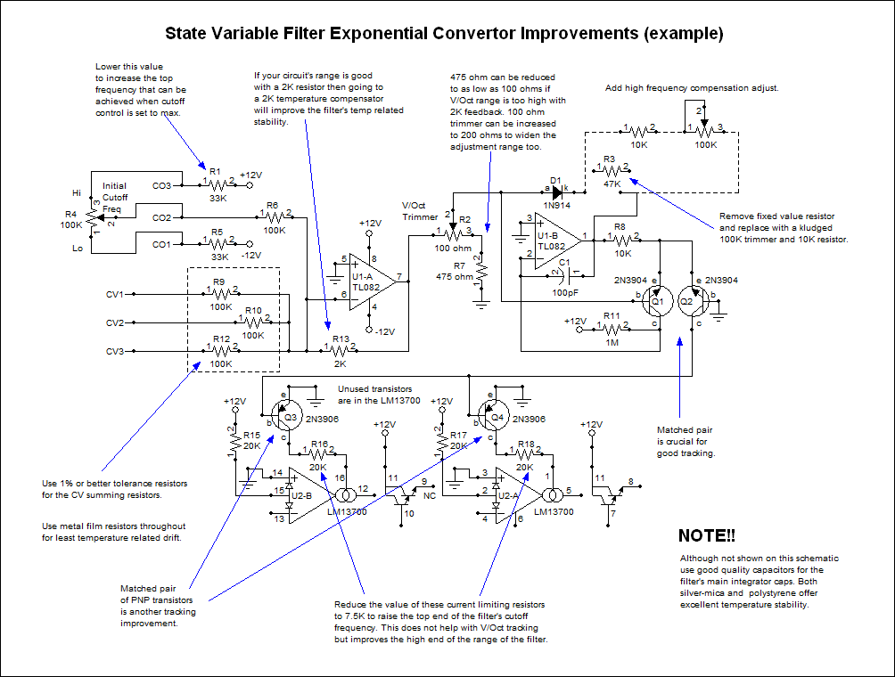
View as PDFHere we see the MFOS State Variable 12db/Octave Filter linear voltage to exponential current convertor section. As with all things DIY it is good to go back and revisit circuits after we have used them for a while. Hopefully we're all reading and continuing to learn more and more about electronics so we can understand how to build cooler and cooler things. I like being able to use this filter as a sine oscillator but I found that I needed better 1V/Octave tracking and a higher frequency response so I put it on the bench and started prodding.
Getting Better 1V/Octave Tracking
First I'll cover the tracking improvements. The voltage summer made up of U1-A and the 100K resistors connected to it's non-inverting input and the 2K feedback resistor are important components. It's best to hand match the 100K resistors to as tight a tolerance as possible or buy and use 0.1% resistors (which you can get from MFOS). Using a 2K tempco for the feedback resistor (R13) is a good way to improve temperature stability however there are some caveats. I found that when I used a matched set of 2N3904 NPN transistors that R2 (100 ohm trimmer) was not able to trim the voltage from the output of U1-A low enough to get the filter in tune at times. The octaves were quite sharp even when R2 was adjusted so as to provide the most attenuation of the output of U1-A. Not to worry you can still use the 2K feedback resistor in this case but you need to adjust the values of one or both of R2 (100 ohm trimmer) and R7 (475 ohm resistor). To allow the trimmer to divide the output voltage of U1-A even more you can reduce the value of R7 but I would not go lower than about 200 ohms. The TL082 (TL072 is a newer/better version) op amp can drive the 300 ohm load since the voltage on U1-A's input is reduce by a factor of 50 (e.g. 1V in = -20mV out). Another way to reduce the voltage at the wiper of R2 would be to increase trimmer R2's value to say 200 ohms or 300 ohms. These measures help you to reduce the voltage on the wiper of R2 while still using a tempco. The obvious thing to do would be to reduce R13 to say 1.8K or 1.5K but if you can stick with a tempco you will be better off. If you have tempcos in these lower values then use one of them and leave R2 and R7 as they are. And again this is if you are not able to adjust the scale properly (octaves are sharp) with the original values of R2 and R7.
To use an SSM2210 or not? I have found that I get consistently good performance from a pair of matched 2N3904 transistors and that I have gotten mixed results with the SSM2210. I know, I know, its from Analog Devices and has great specs and I love them. However I have had really good results using them in filters at times and at other times not. I wish I knew exactly why but I don't and so I go on a case by case basis and when the SSM2210 improves tracking I use it, when I run into weird results I don't. If my knee hurts on a particular day I know it's either going to rain or I shouldn't use the SSM2210 that day... there, see... it's very scientific.
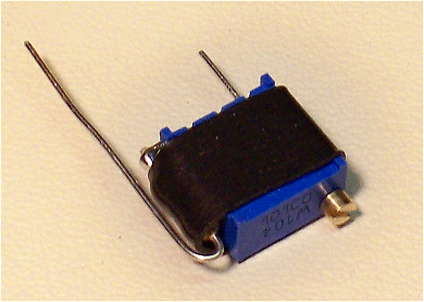
The filter has a fixed high frequency compensation network consisting of D1 and R3. In order to tune the filter to be accurate in the higher registers (and by higher I'm talking 4KHz to 8KHz or so) you need to replace the fixed resistor R3 with a 100K trimmer and a 10K resistor in series as shown in the schematic. I found that a normal Bourns multi-turn trimmer with top adjust (or equivalent trimmer) and a 10K 1/4W resistor could be adapted to fit in the space where the original fixed resistor was.
| Resistor attached to one end of the trimmer's resistive element and it's wiper. | Heat shrink applied to hold the assembly together |
 |
 |
|
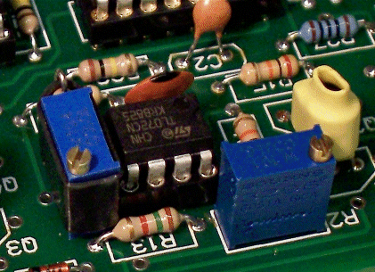
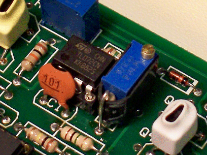
The trimmer and resistor kludge installed. I use heat shrink tubing to bring the matched pairs into the same micro-temperature environment. Whether you use a tempco or not it is important to keep the matched transistors at the same temperature. Hey.. is that a ceramic cap for C2 when you're telling everyone to use silver-mica or polystyrene? Better caps are definitely on order so stay calm. |
The trimmer and resistor kludge installed. Be careful not to short the leads of the trimmer to the top donut where the resistor is inserted. |
 |
 |
A matched pair of 2N3904 NPN transistors for Q1 and Q2 is essential to get the filter to track at all. But along with that I also matched the two 2N3906 PNP transistors (Q3 and Q4) and recommend the same if you want the best tracking possible.
I suggest that you use metal film resistors throughout the filter for best temperature stability.
Getting Higher Frequency Response
Regarding improving the top end of the filter's frequency response I recommend these changes. R1 is the resistor that determines the top end of the voltage fed into the filter as the initial cutoff frequency control. In order to get the cutoff frequency control to allow the filter to go higher I reduced the value of R1. How much you reduce it is up to you down to and including shorting it with a jumper. However it is also important to decrease the value of the two resistors which limit the current into the LM13700's bias inputs to 7.5K. At 20K they are to high to allow the full current from the expo convertor to flow through them. Reducing them allows the top end of the current from the expo convertor to flow and voila higher cutoff at maximum cutoff setting.
Use the best caps you can for the integrator caps (not shown here but they are C2 and C3 220pF caps) from a temp stability standpoint. In my book this means polystyrene or silver mica both of which are very temperature stable.
Filter 1V/Octave Cutoff Frequency Calibration
Calibration is not hard but can be time consuming and a bit tedious. The MFOS Volts Per Octave calibrator takes a lot of the tedium out of the process. In actual practice the filter's frequency will be drifting a bit while you do this procedure so when I say to adjust the frequency I mean get it as close as possible to the starting frequency. What is important is that as discrete steps of 1V are applied to the filter's CV inputs the frequency doubles (goes up an octave) from it's previous value.
- I like to listen to, observe on an oscilloscope, and watch a frequency counter when doing this procedure. So... connect the output to an amp, a scope, and a frequency counter.
- With no inputs to the filter adjust the resonance control to maximum which should result in sine oscillation.
- Adjust the cutoff frequency to between 1KHz and 2KHz.
- Adjust the 100K high frequency compensation trimmer until the frequency starts to increase and then adjust it all the way in the opposite direction. The purpose of this step is to make sure that the high frequency compensation is at minimum.
- Feed in 0V of control voltage on one of the CV inputs.
- Adjust the cutoff frequency to about 40 Hz.
- Increase the applied control voltage to 1V. The target frequency at this point should double to 80 Hz.
- Iterate between 0V and 1V while adjusting trimmer R2 until 0V results in 40 Hz and 1V results in 80 Hz.
- Iterate between 0V, 1V, 2V and 3V while adjusting trimmer R2 until 0V results in 40Hz, 1V results in 80Hz 2V results in 160 Hz and 3V results in 320 Hz.
- Apply 0V again to the CV input.
- Adjust the cutoff frequency to about 40 Hz.
- Increase the applied control voltage to 5V. The target frequency at this point should be 1280Hz.
- Iterate between 0V and 5V while adjusting the 100K high frequency compensation trimmer until 0V results in 40Hz and 5V results in 1280Hz.
- I find that I normally have to iterate over this procedure a few times to find the best compromise between good tracking at low frequencies and decent tracking at higher frequencies. The goal is to get as much tracking range as possible.
- The MFOS Volts Per Octave Calibrator really helps as far as applying the 1V steps is concerned and when set to repeatedly
sequence over the steps it is easier to tweak the trimmers and immediately hear the affect on the tracking.
Four Pole Low Pass VCF 1V/Octave Tracking & Range Improvements
View as PDFPlease read the previous description since much of it applies in principle to this design as well and is not repeated here. I'm betting you can already tell what I'm going to say regarding improving this VCF so I won't be as verbose as before. The same advice applies regarding the CV summer, the 2K tempco and the values of R5 and R8. Again I recommend kludging in the 100K high frequency compensation trimmer and 10K resistor combination in place of the fixed R2 47K resistor. Matching of VBE to within 2mV for Q1 and Q2 is critical and I recommend as above that the four 2N3906 PNP transistors (Q3, Q4, Q5, and Q6) also be matched to within 2mV of one another. This is done by matching the four of them against a separate 2N3906 PNP again so that all VBEs are within 2mV of the control PNP. Be wary that as you are matching the transistors against the control PNP that the sign (+ or -) of the difference is always the same. If one PNP matches againg the control with a difference of -1.5mV then all of the others must also have a difference within 2mV and with the same negative sign. Reduce the values of the bias input current limit resistors to 7.5K to allow more current to pass into the bias inputs. This will increase the top end of the filter's frequency response. Lower the value of R1 as necessary to obtain the highest cutoff (with a limit of 20KHz). You may not get to 20KHz but my suggestion is not to go beyond it if the frequency gets that high.
Calibration is the same as described above except you adjust R5 for scaling and the kludged in 100K trimmer for high frequency compensation.
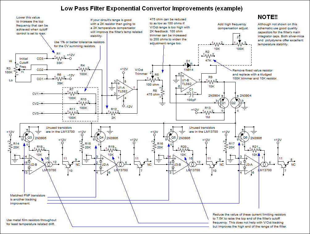
As I mentioned these same improvements apply to the VCFs in the Sound Lab Mark II, Sound Lab ULTIMATE, and the Sound Lab ULTIMATE EXPANDER. You just need to compare those schematics to these and you'll easily find the corresponding components to change the values of, replace, etc. Good tweaking!