Ray Wilson authored this content while he was actively running MFOS as the founder and resident genius.
We retain the content because it reflects a valuable point of view representing that time and place.
Article by Ray Wilson
Introduction
| Interfacing MFOS gear with your synthesizer is not hard but you need to know the expected gate and trigger requirements of your synth in order to successfully integrate it with MFOS gear. MFOS gear emits gate and trigger pulses that usually start at ground and rise rapidly to the MFOS module's positive supply voltage (or very near it). MFOS gear control voltages can go higher than +/-5V which is the limit for some commercial analog gear. In order not to put too high of a voltage into your gear this article shows how to limit the CV output of MFOS gear to +/-5V. Lastly your gear may not have a high enough gate or trigger voltage to gate and trigger MFOS modules. I show how to boost low gate and trigger levels to those needed by MFOS gear. MFOS gear can more than likely take the control voltage output by your synth with no problem but do not apply control voltage to MFOS gear that is higher or lower than the MFOS modules's positive or negative supply voltage respectively. |
|
The circuits below that require power should be powered from the MFOS module's dual power supply. These circuits could be built into a patch bay type of device that could be used in a generic interfacing patch setup.
Some MFOS gear already has comparators on the gate and trigger inputs which will not need pre-boosting. Consult the schematic to see whether the gate/trigger boost is needed. If there is not a comparator or transistor amplifier on the gate/trigger input of the MFOS module then it will most likely need boosted.
Limiting MFOS Gate and Trigger Levels
Limiting the gate/trigger voltage levels is as easy as applying a resistor and zener diode to the output of the MFOS module. I show a 5V zener diode but you can select the zener diode for whatever voltage you need, either higher or lower. Remember that zeners are approximate in value and will vary 100s of millivolts from the ideal. The 3K resistor limits the current through the zener as well as what is delivered to your synth's gate/trigger input. If your synth's gate/trigger current requirement is greater than what can be put through 3K I'd be very surprised.

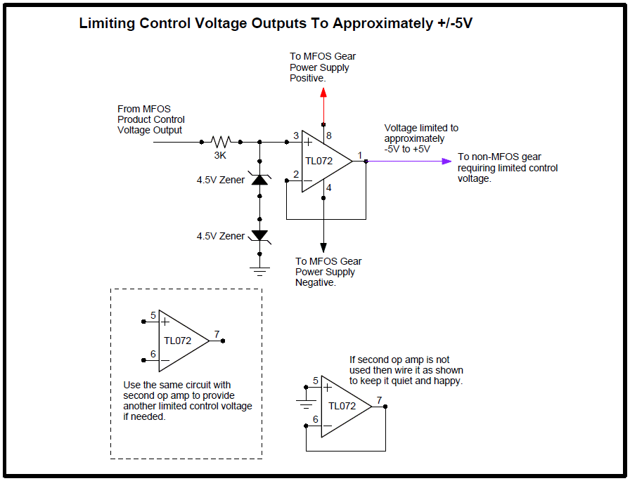
Limiting MFOS Control Voltage Outputs
Limiting the MFOS control voltage output requires back to back zeners as shown. This circuit allows voltage to be delivered to the non-inverting input of the op amp unchanged until the level of the voltage goes above or below the zener voltage plus one diode drop. When one zener turns on the other acts like a normal diode, and vice versa. The buffer op amp insures that the 3K current limiting resistor won't interfere with your synth's CV input requirements. Without the op amp buffer, if 3K was put in series with a 100K control voltage mixing resistor the V/Oct would be off by 3% which is definitely noticeable. Using the op amp buffer, until either zener breaks down the voltage fed to the output of the buffer will be the same as what is being delivered from the source CV.

Boosting Your Synth's Gate/Trigger Output Levels
Here we use a comparator to boost the gate/trigger of your synth to the level required by MFOS gear gate and trigger inputs. As mentioned above more recently developed MFOS modules have a comparator on the gate/trigger inputs and will not need boosted. Consult the schematic to see if the module you are interested in has comparator input or not.
The voltage fed to the non-inverting input of the op amp used as a comparator is 2V when the unit is powered with +/-12V. If you power your MFOS modules with +/-15V then make the larger value 13K instead of 10K. When the voltage fed to the non-inverting input goes above this "threshold voltage" plus a little extra due to the hysteresis provided by the positive feedback resistor (2M) the output of the comparator shoots from negative saturation to positive saturation forward biasing the 1N914 and dropping the positive saturation voltage (minus a diode drop) onto the 4.7K resistor. When the input voltage is less than the threshold + hysteresis voltage the output of the op amp stays at negative saturation reverse biasing the 1N914. At that time the output sees ground through 5.7K of resistance.
In some cases two CD40106 hex inverters connected in series may be necessary in order to give the gates and triggers being fed to the MFOS gear CMOS characteristics. CMOS outputs both source and sink current. Without the added CMOS buffering the op amp, when saturated high, will source current through the 1N914 diode and 1K resistor. When the output of the op amp comparator is low current will be sinked through the 1K resistor and 4.7K resistor to ground. If the MFOS module you are driving requires CMOS characteristics you may need the CMOS buffering.
