Ray Wilson authored this content while he was actively running MFOS as the founder and resident genius. We retain the content because it reflects a valuable point of view representing that time and place.
Article by Ray Wilson
Introduction
Have an interest in analog synthesizers perhaps wishing you had one or could build one? Well you've come to the right place. MFOS' mission is to help you realize your analog synthesizer dreams so here is some basic information about analog synthesizer modules. There's more than enough to get you started. The "Music From Outer Space" website has tons of analog synthesizer plans and schematics for you to build once you get your feet wet. Bear in mind that you do need a fair amount of electronics knowledge and kit building experience to get started but it's never to late to learn something new or reignite an old passion or hobby. As I always say... "Keep imagining, keep inventing, stay ingenious!"
NEW! - Make: Analog Synthesizers is Here! | ||
|
||
|
The "Make: Analog Synthesizers" Book Story
|
Generic Synthesizer Block Diagram
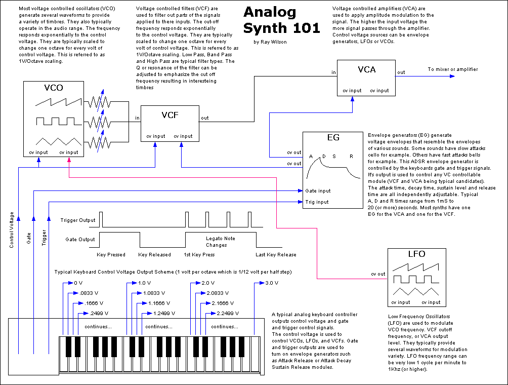
The most common analog synthesizer setup is shown below. There are usually one or more VCOs (Voltage Controlled Oscillators), one or more VCFs (Voltage Controlled Filters), one or more VCAs (Voltage Controlled Amplifiers), one or more Signal Mixers, one or more Envelope Generators and one or more LFOs (Low Frequency Oscillators) and a White Noise Source.
A typical signal chain would be as follows: One or more VCO waveform outputs are typically fed into a signal mixer the output of which is fed into a VCF, the output of which is fed into a VCA the output of which is fed into the mixing board for listening or recording.
A keyboard controller is also an important part of the system. It's job is to output precision voltages at a scale of one volt per octave to be used to control the VCOs and VCFs. The keyboard control voltage as it is called is connected to the exponential control voltage inputs of the VCOs and optionally the exponential control voltage inputs of the VCF. The keyboard also emits two other important signals. They are the Gate and the Trigger signals. The gate is an electrical level that changes state when the user has a key held down. A typical setup might be that the gate output will be at ground level with no key pressed but when a key is pressed the gate output goes to a high level (5V for example).
The gate signal is used to control the envelope generators that modulate the VCF and VCA. When a key is pressed the gate signal goes high causing any envelope generator(s) connected to it to begin their attack cycle(s) and remain at their sustain level(s) until the gate is released. When all keys are released and the gate signal goes low (back to ground) any envelope generator(s) connected to it will begin their decay cycle(s). The trigger signal (a several millisecond long positive going pulse: 0 to 5 volts for example) emits a pulse when you go from a no key down to a key down scenario and any time the note is changed (whether all keys are released or not). Some envelope generators allow trigger pulses to restart their attack phase once the decay phase is entered without the need to see a low gate level.
It is the modulation provided by the envelope generators that give a synthesizer it's organ-like capability of only being heard when a key is pressed. Of course the envelope generator control of the synthesizer's VCA and VCF give a lot more variation in how that note comes on and goes off and which harmonics are emphasized.
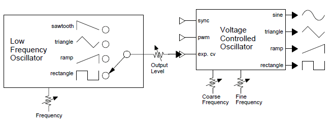
The LFO is used to provide several modulation waveforms that can be used to modulate the VCOs, VCFs, VCAs, in short anything that can be controlled by changing voltage.
The noise source provides white noise for making sounds like wind, surf, thunder, rain, etc.
MFOS Sound Lab Mini-Synth Mark II Analog Synthesizer Block Diagram
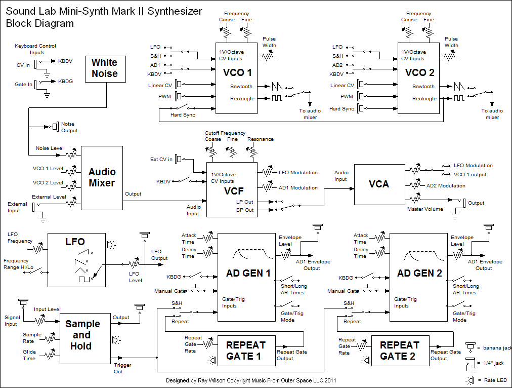
This block diagram shows the internal components (or modules) that comprise the MFOS Sound Lab Mini-Synth Mark II analog synthesizer. The modules shown in the diagram are explained in more detail below and there are some sound samples you can listen to. The analog synthesizer module complement usually includes one or more of the following: voltage controlled oscillator (VCO), white noise generator, voltage controlled amplifier (VCA), voltage controlled filter (VCF), envelope generator (AD(R) EG), low frequency oscillator (LFO), keyboard voltage controller (not shown in this diagram but explained below), and an audio mixer. The audio mixer combines the output of the VCOs, White Noise, and external input prior to further processing through the VCF and VCA. There are many more analog synthesizer modules but these are the basic set and you can do some very impressive sounding things with this basic set of modules. At the bottom of this page there are links to songs that were produced featuring the very synthesizer shown in this diagram.
And if you're interested here is complete information for building the MFOS Sound Lab Mini-Synth Mark II.
Further Information About Common Analog Synthesizer Modules and Sound Samples
Attack-Decay (Release) Envelope Generator
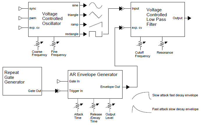
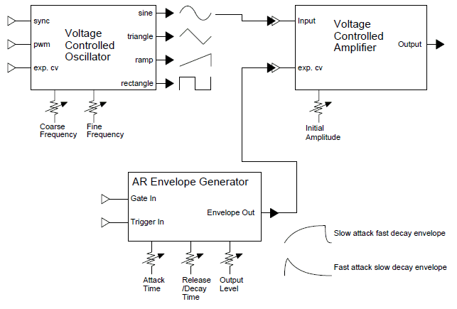
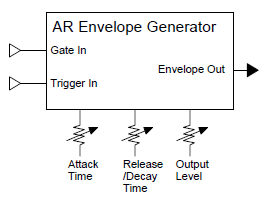
The attack decay (release) envelope generator is the simplest of the envelope generators. There are more advanced envelope generators that have more states thus giving you more control over the envelope used to modulate a module (or modules). The envelope generator is designed to create a modulating voltage whose attack time (time the voltage takes to go from it's low level) to it's high level is adjustable as is it's decay time. In other words let's say our envelope generator's normal output is zero volts. When the envelope generator is triggered (a sharp positive pulse is applied to the trigger input) the output voltage will rise at the rate set by the attack time control to it's most positive voltage (we'll say five volts for our example) and then it will decay back to zero volts at a rate set by the decay control. We can set it to produce fast attack and slow decay, slow attack and fast decay or anything in between. The output of the attack decay envelope generator is used to control other modules. For example, say an AD(R) envelope generator's output is connected to the control voltage input of a voltage controlled amplifier and a 1000 Hertz sine wave is connected to the VCA's input. You can make a sound like striking a small bowl, kind of a ding... that fades away if the attack time is short and the decay time is long. If you change the attack time to be long and the decay time to be short then you'll get the effect of a violin that fades in slowly.
You can also use the AD(R) envelope generator's output to control a VCF, VCO, VCA, as input to a Sample & Hold, basically any thing you want to modulate using the envelope voltage. Why do I keep calling it an Attack Decay (Release) envelope generator? Because when you activate the AR generator with a gate it remains high until the gate is released at which time it decays. When you activate it with a trigger the output attacks and immediately decays after the output reaches it's high level.
Low Frequency Oscillator - LFO
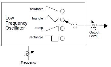
The low frequency oscillator is used to produce slowly changing voltages of various waveforms for modulating other modules. Whereas the VCO produces frequencies in the audible range (although many can go very low in frequency and can be used as LFOs) the LFO produces frequencies whose period can be as long as seconds or even minutes. LFOs typically produce a variety of waveforms including sine, square, ramp, triangle, and sawtooth.
Sample & Hold
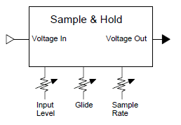
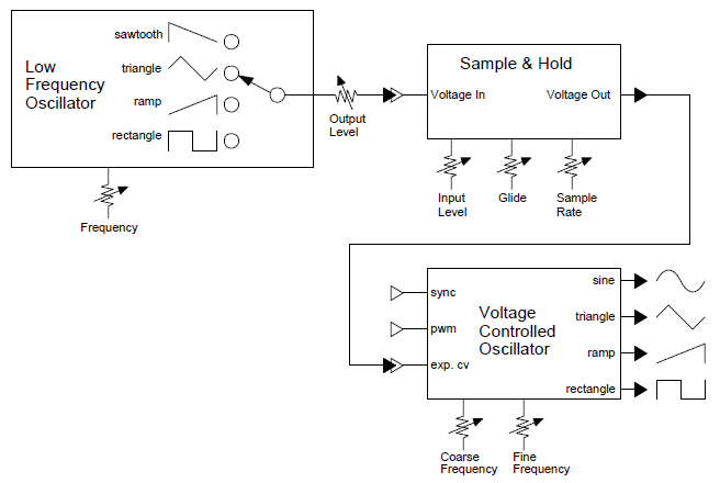
A sample & hold module is a very interesting device. You connect a modulating voltage to the input and the sample and hold takes regular samples at a rate set by the user and routes the sampled voltage to the output. The sample taken is typically less than a millisecond or shorter but the hold time can be very long. Hold times are finite since the sample and hold relies on a capacitor to hold the sampled voltage and all capacitors have leakage no matter how minuscule it may be. If you were sampling the output of an LFO's triangle waveform and the sample rate was 10 times higher than the frequency of the LFO the sample & hold's output would appear on an oscilloscope as a stepped triangle.
Keyboard Voltage Controller
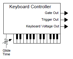
The keyboard voltage controller is the device you use to play traditional 12 tone music with a synthesizer. The main difference is that often an analog synthesizer is monophonic (one note at a time) as in no chords allowed. If you happen to hit two notes at a time the keyboard outputs the voltage corresponding to the lower note (this is known as low note priority). Keyboard controllers can come with anywhere from one octave of keys to as many as you like (73 keys is pretty much the top end for analog synths) The keyboard controller has several outputs: gate, trigger and control voltage (normally more than one). The control voltage is usually one volt per octave meaning that if when you press the first, or lowest, key and you get 0 volts then pressing the octave of that key will cause the controller to output one volt and the octave of that key will cause the controller to output two volts etc. The voltage steps between half notes is .08333 volts or 1/12 of a volt. There is usually a glide or portamento control that causes the voltages output by the controller to slew from one to the other (think slide whistle). You can set it from no portamento to seconds long portamento. The gate output is normally a low voltage until you press a key at which time it goes to a high voltage (5 to 10 volts or so). When you release the key the gate output goes low again. The trigger output emits a pulse when you initially press a key and any time you change notes thereafter. Even if you play in a legato fashion (never letting all keys up at once) the trigger output emits a pulse when the output voltage changes. The gate on the other hand will stay high if you don't remove all fingers from the keyboard. The gate and trigger outputs are used to trigger and gate devices like AR envelope generators or ADSR generators. The gate used with an Attack Decay (Release) generator will cause the output of the envelope generator to maintain a high level as long as the key is pressed and then when the key is released (gate goes low) enter the decay cycle. The trigger output fed to an AR envelope generator will cause it to attack and then immediately decay.
Voltage Controlled Oscillator
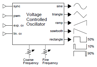
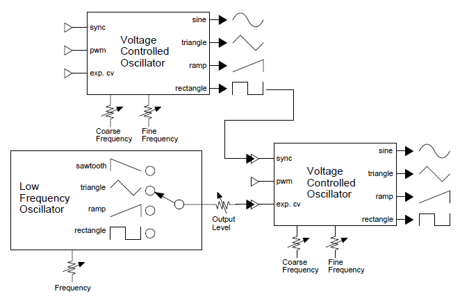
Here we see a block diagram of a voltage controlled oscillator. It is one of the most basic yet most important modules in an analog synthesizer. The VCO, as it is called, is the main tone generating module in a synthesizer. It is responsible for generating the oscillatory electronic signals (known as waveforms) that make up the main pitched sounds that a synthesizer produces. The complement of waveforms can vary from synthesizer to synthesizer but typically included are: sine, rectangle (square and pulse waves), triangle, ramp and sawtooth.
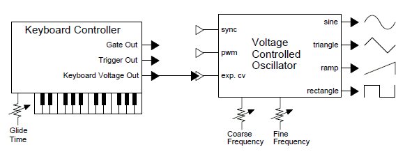
The waveforms from the VCO are usually put through other modules to modify and modulate their amplitude and harmonic content. Additionally the VCO has several inputs that permit modulation of it's frequency. One of the important modulation inputs to the VCO is it's exponential control voltage input. These inputs (there are usually several) allow the VCO to be controlled by external equipment (keyboards, sequencers, MIDI to CV converters, etc.) such that you can "play" equally tempered music with the oscillator. All of the exponential CV control inputs are applied to a DC voltage summer (DC mixer) whose output is fed to the succeeding linear voltage to exponential current convertor. The standard for this voltage is 1V per octave which means that as the voltage applied to the exponential CV input is increased from say 1V to 2V the frequency changes by 1 octave. More than that when you take that 1V and chop it up into even increments of 1/12V (or .08333V) the VCO responds by increasing it's frequency one musical half step for each increment. So when you step from 1V to 2V in .08333V increments (i.e. 1V, 1.0833V, 1.1666V, 1.24999V ... 1.91667V, 2V) the VCO steps up from it's initial frequency at 1V to that frequency's octave (or twice the initial frequency) in musical half steps. The miracle doesn't stop there though, as you continue to apply steps of .08333V and continue to land on successive integral volt values (i.e. 1V, 2V, 3V, 4V, 5V etc) the frequency continues to follow the musical scale octave after octave. The trick is the VCO's linear voltage to exponential current converter which just happens to provide us with this amazing property. Bear in mind that the VCO is a sensitive device and taking it from a cold place to a hot place can cause the 1V/octave tracking to be sketchy.
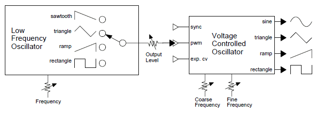
The pulse width modulation control voltage input applies to the rectangular waves output by the VCO. It changes the the width of the square wave's high time (this is also called duty cycle) usually from about 10 percent high to 90 percent high. The actual percentages can vary from synth to synth. The closer to 50% the high time is the more hollow sounding the waveform is. A 50% duty cycle is known as a square wave. At narrower pulses more harmonics start to make their way into the waveform and it sounds reedier and reedier as it gets narrower. By modulating the pulse width you can make one oscillator sound like two because the varying duty cycles mimics the effect of two oscillators tuned close together that beat against one another.
The sync input (hard sync in the samples) accepts a hard edged waveform (normally square or pulse but sawtooth or ramp can work in some instances) and one of the edges (depending on the design) causes the oscillator's ramp core to reset to 0V and begin it's ramp again. The effect is hard to describe but the synced oscillator produces additional overtones that sound really cool.
The linear (lin cv) input permits the oscillator's frequency to be controlled in a linear fashion. Instead of the frequency doubling for each change in 1V the frequency increases (or decreases) linearly in response to control voltage. For example with exponential control you expect the frequency to go up like this for example: 1V = 100Hz., 2V = 200Hz. 3V = 400 Hz., 4V = 800 Hz. But with linear control the frequency increases like this (again as an example) 1V = 100Hz., 2V = 200Hz. 3V = 300 Hz., 4V = 400 Hz. The result is that the VCO's frequency is modulated less when using linear voltage control than when using exponential control voltage. Often this is useful when applying a vibrato effect from an LFO. The modulation is more subtle and again the curve of voltage to frequency is linear.
|
|
|
||||
|
|
|||
|
|
||||
|
|
||||
|
|
|||

|
|
|||
|
White Noise Generator
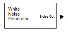
White noise is used in analog synthesis for a variety of reasons. It makes a great base for sounds like rain, wind, surf, thunder, explosions, steam, chiff sounds, etc. It can also be used as a modulator for other modules and as a great source of random voltages when it's instantaneous level is sampled and held by you guessed it, a Sample & Hold module. Analog white noise is generated by reverse biasing the emitter base junction of an NPN transistor and amplifying the signal that occurs at the emitter. I like to think of it as the sound of trillions of electrons randomly bashing into one another on a micro scale. There are digital techniques for generating white noise but they often result in a repeating pattern that is audible. True white noise is really random in nature and never ever repeats a pattern (as far as we know).
|
|||
|
|
|||
|
Voltage Controlled Low Pass Filter
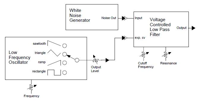
The voltage controlled low pass filter is one of my favorite modules because of it's ability to modify the harmonic content of the signal applied to it's input. The low pass response passes all frequencies that are below a certain frequency known as the cutoff frequency. The cutoff frequency is voltage controllable which means the harmonic structure of the wave passing through the VCF can be controlled dynamically. Additionally the resonance or amount that the filter emphasizes the signal near the cutoff frequency is adjustable. With low resonance the filter does it's job and you can hear the higher harmonics of the signal fed into the filter as the cutoff frequency is increased. For example, at a really low cutoff frequency (e.g. less than 10 hertz) a 100 Hz. square wave would hardly make it through the filter but as the control voltage is increased the fundemental frequency of the square wave would start to poke through but with all of it's high harmonics subtracted it would begin to look like a sine wave. As the cutoff frequency is increased the harmonics start to emerge until you hear your good old square wave. But... turn up the resonance and things get interesting. Now the cutoff frequency is emphasized and the filter begins to ring (almost oscillate at the cutoff frequency) which adds even more interesting harmonics to the waveform as the filter's ringing adds to the original waveform's harmonics. The higher the cutoff frequency is made the more the effect is heard resulting in the familiar wah sound.
But there is more... in some filters when you turn the resonance up high enough the filter actually begins to oscillate with a sinusoidal waveform. If the filters control voltage processor is designed to provide exponential current in response to the linear voltage applied to it's CV input the filter will track 1V per octave just like a voltage controlled oscillator. It's a great source of very pure sine waves. Bear in mind that the VCF is a sensitive device and taking it from a cold place to a hot place can cause the 1V/octave tracking to be sketchy.
|
||||||
|
|
Voltage Controlled Amplifier
The voltage controlled amplifer is a mainstay of any synthesizer and does one basic thing which is control the amplitude of the signal passing through it under voltage control. The lower in magnitude the voltage applied to the VCA's CV input the lower the amplitude of the signal passing through it. The higher in magnitude the voltage applied to the VCA's CV input the higher the amplitude of the signal passing through it. Of course the VCA can be dynamically controlled just like most modules in an analog synthesizer.
|
||||
|
|
The Incredible Google Doodle for Robert Moog's 78th Birthday
In tribute to Robert Moog, the Google Doodlers outdid themselves with this totally cool Google Doodle application. Hats off to the Google Doodlers! There is more to this than meets the eye. PLAY WITH IT! Google has developed a totally cool synthesizer and 4 track tape system and put it IN YOUR BROWSER TO PLAY WITH... INCREDIBLY COOL!!!
Google's Totally Cool "Robert Moog's 78th Birthday" Doodle
Some Analog Synthesizer Music You Might Find Enjoyable
These are some classical songs (and one soundscape) I produced using the MFOS Sound Lab Mark II and Sound Lab ULTIMATE.
Here is a nice collection of various analog synthesizer styles including space music and environmental sound. There are still more realms that include noise, and completely non-tonal "music" to explore.
Some Analog Synthesizer Books You Might Find Informative
Here are a number of books that can help you learn more about analog synthesis. I suggest that you search on Amazon when you get there because new books comes out all the time and new book associations seem to come up all the time as well. Only by sitting down (or standing, or laying down, or whatever reading posture you prefer) and reading about the intricacies of analog synthesis will you be able to determine what modules you would like to have in your very own dream analog synth.
Good learning... Ray
