Capacitors are usually measured in microfarads abbreviated uF (1 uF = .000001 Farad) and picofarads, abbreviated pF
(1 pF = .000000000001 F).
Capacitors (or caps) are used in timers, filters, interstage coupling, power supplies, motors, etc.
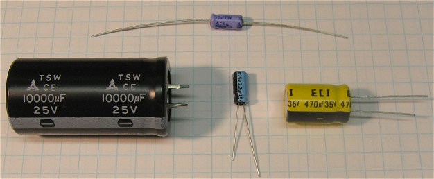
The working voltage of a capacitor is the voltage that can safely be applied without breaking down the dielectric material and causing the capacitor to short and be destroyed. When building a circuit be sure to buy caps that have a working voltage that is at least equal to or preferably somewhat above the highest voltage you plan to apply. Using caps with higher working voltage than you plan to apply is fine and is normally the case. Using caps with a lower voltage rating than you plan to apply is asking for trouble and can cause real damage if say you are using low working voltage caps in a power supply and one side of a supply becomes shorted due to a capacitor failure. In other cases capacitor shorts can result in complete loss of circuit function or degradation of circuit function. Caps come with ratings like 16V, 25V, 35V 50V etc.
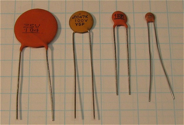
Size is another factor that comes into play as higher working voltage caps can be larger than their lower voltage counterparts. Most MFOS PC boards use a 0.2" lead spacing for the ceramic caps (which usually come in 25V to 100V working voltage). The electrolytic caps can vary and you should look at the PC board to see what will fit comfortably. Part leads are easy to form and as long as the board has room for them you can use whatever caps you can fit on the PC board. In other words when you find a super deal on a cap you want/need don't pass it up just because you may have to form the leads a bit to get it to fit on the board.
The value of a cap can usually be changed by 10% or more and the circuit will still work perfectly. When a schematic calls for 0.002uF cap and all you can find is 0.0022uF cap don't panic it will work just fine (other examples: 0.02 specified 0.022 will again work fine, 0.03 specified 0.033 will work fine... etc.) Caps normally come with a tolerance of 10% to 20% so using a value very close to that specified in the schematic will normally not even be noticed in the final circuit's function. Of course if the circuit is some critical timing circuit then try to find the specified cap but ALL of the circuits shown on MFOS will be fine with cap changes in the 10% to 20% range with very little if any noticeable functional changes.
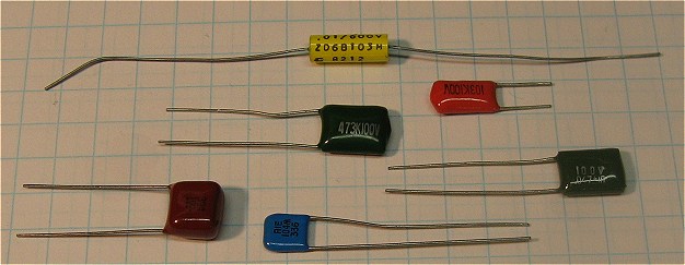
A notable exception to the cap tolerance comments made above is when you are selecting caps for a two or four pole voltage controlled filter. Use caps that are as close to the values specified as possible in those cases because the function of the filter is improved by having matched caps in the filter's pole circuits. The closer the caps are to one another in value (typically the case in two or four pole filters) the better the filter will work. Use of a capacitance meter to measure and match your caps when making a VCF is definitely warranted. Use of temperature stable film caps is a good idea for VCFs and VCOs (polycarbonate or polystyrene).
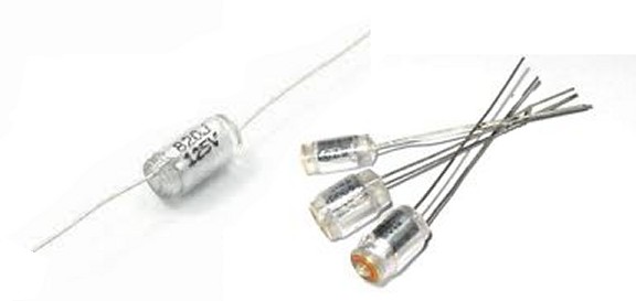
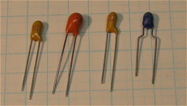
Always observe polarity markings when using polarized capacitors. In most cases the negative lead is marked with minus symbols but in others (tantalum caps for instance) there is a + symbol denoting the positive side. Another convention is that the positive lead is usually longer when you buy brand new caps but this may not be the case with surplus caps that have already had the leads trimmed or have been removed from equipment. Electrolytic polarized caps do not take kindly to having the voltage applied in the wrong polarity. Tantalum caps for instance will become leaky and useless if polarity is applied incorrectly. Tantalums can also go off like a firecracker (no exaggeration) sending shards flying. Aluminum electolytic caps will act like low value resistors and can burn out diodes in power supplies by drawing excessive current.
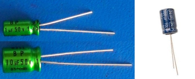
Bipolar (or non-polarized) capacitors use aluminum electrolytic chemistry to get high capacitance but their plates are arranged so as to avoid polarization. They look very much like aluminum electrolytic caps but they will not have a plus symbol (+) or negative symbol (-) on the case. They may have the letters: BP or NP.
When you are just starting out to buy your own components (weaning yourself from kits) I suggest you find caps at surplus houses like All Electronics at first so you get an inexpensive chance to see various caps and start to form a preference on the type and size you find most useful. Keep a notebook with parts and suppliers so that each time you order it becomes easier and takes less time. Many sites (Jameco, Mouser, etc) remember your previous orders and after a while ordering is simply re-ordering with the click of the mouse.
Sometimes you need a capacitance value that you don't have on hand. You can put capacitors in series and/or parallel to produce different values. This image shows the formulas for obtaining values from capacitors by placing them in parallel (adding mode) or series (dividing mode). Placing caps in parallel essentially adds the plate areas together and voila higher capacitance. Placing caps in series essentially puts more space between the plates and voila lower capacitance (note it is always lower than the lowest value cap in series).
A trick to remember for simulating "bipolar" or "non-polarized" caps is to use two polarized caps in series with the negative poles tied together. The values of course divide according to the series capacitance formula show below. When you use two capacitors with the same value the capacitance is simply divided in two.
| Capacitor value prefixes fall here in decimal representation. | |||
| milli | micro | nano | pico |
|---|---|---|---|
| .000 000 000 000 | .000 000 000 000 | .000 000 000 000 | .000 000 000 000 |
Some examples


There is a type of aluminum cap that looks very much like a polarized aluminum cap that is known as a "non-polarized" or "bipolar" aluminum cap. These types do not have polarity markings and provide a lot of capacitance in a reasonably sized package where you need non-polarization.