Ray Wilson authored this content while he was actively running MFOS as the founder and resident genius.
We retain the content because it reflects a valuable point of view representing that time and place.
Article by Ray Wilson
So You Made A Board and It Doesn't Work... Now What?Occassionally I will get an email that goes something like this: "I built the - fill in the project - and it doesn't work. I built it just like the site showed. Which wire did I forget? Which component is bad? What's wrong with my project?" First off let me assure you that having a problem in a circuit is not unusual and that if you intend to continue working with electronics you will definitely need to cultivate the skill of trouble shooting. Trouble shooting is the logical approach to finding a problem in an electronic circuit and with practice you will get better at it. When your circuit presents you with an opportunity to learn to troubleshoot remember the immortal words emblazoned on the cover of Douglas Adam's Hitchhiker's Guide to the Galaxy - DON'T PANIC. Rest assured that I have built each and every project on the site (often many times) using the material published on the site and they all work quite well. I'd also like to take this opportunity to answer everyone that asks this question: I built the fill in the project just like you said but nothing works - which component do you suspect is the one causing my particular problem? I don't know about other synth designers but when I design a circuit my primary concern is finding the component values that make the circuit work properly. I think some people envision me spending long nights putting the wrong value component at every location in the circuit to see what it will do so I can tell people exactly which component is the problem child just by being told - "I built the unit just like you said and nothing works". I sincerely hope this news isn't too shocking for anyone but, there you go. Even a simple project can present trouble shooting challenges. Time spent in carefully reading the circuit description and following the component placement and wiring diagrams will pay off in projects that work first time when the power is applied. |

|
Find a Local Electronics Guru
If you are having difficulty with a circuit and need trouble shooting help and advice I suggest that you cultivate a relationship with someone at your school, university, family, etc. that has electronic experience and trouble shooting skill. Politely asking for help from a local electronic repair shop might work. You never know when you're going to find a kindred 'synth-diy' spirit. As much as I wish I could, I am not able to provide everyone to whom I sell a PC board or kit with detailed trouble shooting help because there are just not enough hours in the day or days in the year for that matter. I have written complete descriptions of the operation of every circuit on the site and I always suggest a thorough reading of the material before beginning to see if a project is within your skill level.
Laying Out Your Own Boards is Cool But...
When you lay out your own PC board for an MFOS project and have trouble with it I'm afraid you are really on your own. The process I go through to make sure my PC boards work is as follows. First I dream up a module that I need or want in my synth and which I think people will find useful and fun. I then design the circuit and build it on a solderless breadboard to get the bugs out and refine the functionality. When I feel that the circuit is ready for prime time I get a prototype PC board made from my initial PC layout. When the prototype boards come in I build up the module and evaluate it. If everything works - voila - I order production boards and sell them to my customers. If it doesn't I go through the same trouble shooting steps anyone would to find out what's wrong with the board. After I find my errors or omissions and kludge up any necessary fixes I relayout the board to include any necessary changes. After that I order a small batch of production boards - but since I changed the board I do a complete verification build of the new board into a module and once again test it. If all is well (usually the case) I order production boards and sell them to my customers. Typically if there is a problem at this point I will publish the kludge necessary to fix it, sell the boards at a discount and do another PC layout with fixes and order another small batch (and yes... I always do a verification build if the board changes). As you can see it is a rather involved procedure and I don't sell PC boards unless I'm really sure they work. So the bottom line is laying out boards can be problematic if the board has an error in it and you are unaware of it. If your board doesn't work - something is connected to something it shouldn't be connected to or something isn't connected to something it should be connected to - that's generally about the size of it.
Unlike the Who I Can't See for Miles and Miles...
Even a small project can grow to have a large number of interconnections and if any one of them is missing - things won't work. If a component value is not what it should be - things won't work. If a component is bad - things won't work. The additional fact that I can't see very well over distances of thousands of miles is another huge factor. Trouble shooting is best performed on site, in the presence of the equipment with the problem - not through email. I try my best to let people know that the projects require electronics skill and trouble shooting experience up front. If your circuit has a problem you need to methodically work your way through it and find the issue.
So... On to the Trouble Shooting Advice and Pointers
Make sure the power supply is putting out the correct voltage(s). If that's good then trace from input to output looking for the signals described in the circuit's description until you find an anomaly. Your electronic sleuthing skills will grow as you gain experience in finding a problem. One of my electronics instructors from the U.S. Steel Homestead plant would "seed" a problem in a circuit and then let us figure out what was wrong. Friends can do the same thing for one another to help one another grow in trouble shooting skill. With perseverance, logical reasoning, time and a little luck you will find what is keeping your circuit from doing what you want it to do. There is nothing better than the feeling you get when you track down and fix a bug - on your own. It's not magic - it's logic and with practice you'll get good at it.Here are the things I would tell you to look for and do if I was going to give you trouble shooting advice. Trouble-shooting is a necessary skill you must develop if you plan to succeed with electronics.
These tips are not in any particular order so please read the whole page to get the most from the information. It's a three minute read that could save you hours and might just hit the nail on the head regarding the problem your circuit is experiencing.
- Read all of the circuit descriptions and schematics for the project. This is the main information that will help you troubleshoot.
- Only apply power when appropriate during trouble shooting. I know you know this but be aware because its easy to forget.
- Hopefully you have populated the PC board, used good IC sockets and followed the parts placement diagram to a "T". Double check that all IC sockets are facing the correct direction using the parts placement diagram. An incorrectly oriented (backwards) chip will draw enough current to take out a small power supply. All well and good. Have you inserted all of the chips? Well un-insert them because you need to follow the next step.
- Don't apply power or insert chips until you have rung out the power connections with an ohm meter. That is you take your ohm meter (set on the lowest ohm scale) and measure the
resistance between where the power connections enter the board and each IC socket's power pin(s). Do this for V+, V- and ground. Your meter should be set for the lowest scale and should read the same
as when the leads are shorted. If you find one that reads higher than the "leads shorted" value you may have found a "cold" solder joint. These are joints that look soldered but a little gray and
dull. Re-flow any solder joints that appear or measure "cold".
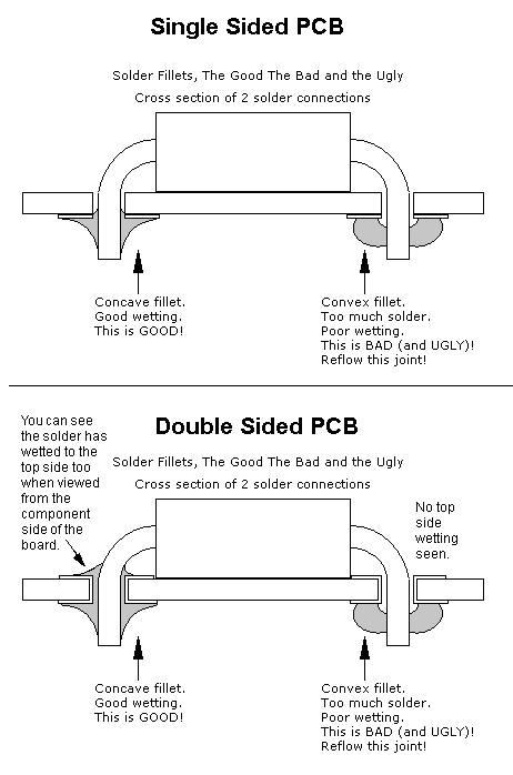
- Cross Sectional View of Solder Joints
Solder joints must be made with care. Too much solder and you might short adjacent pads or traces,
too little and solder joints could come apart leaving you with an intermittent connection. As you can
see from these illustrations that 1) the solder should "wet" (cling) to the surfaces you are bonding and 2)
the solder joint should have nice even fillets: on the bottom only for single sided boards and on the top and
bottom for double sided boards. The joints should appear shiny and it is a good idea to clean up
excessive rosin flux with flux cleaner.
- BEFORE INSERTING THE CHIPS apply power to the board and then use your DVM to measure that you get the correct voltage at each of the chip socket power pins.
- If the board is a multi module board (e.g. ULTIMATE or ULTIMATE EXPANDER or similar type board) REMOVE POWER then insert the chips for one module and then reapply power and make sure that the board does not draw excessive current. Continue on remembering to REMOVE and REAPPLY POWER leaving the chips for the previous module(s) inserted and measuring the current consumption at each step. This will help you isolate incorrectly oriented chips. An incorrectly oriented (backwards) chip will draw enough current to take out a small power supply.
- Use a good resin core solder of the appropriate diameter (smaller is better because you have more control over the amount of solder being applied).
- ALWAYS USE SOCKETS for integrated circuits (swapping to find bad ones is infinitely easier). As Confucius says "Man who use sockets very wise, man who not use sockets like to desolder a lot!"
- Use a magnifier and visually inspect the copper traces for shorts or opens.
- Found a short...? Open it with an Xacto knife (or similar tool).
- Found an open...? Close it with some copper wire and solder.
- Visually inspect the board for unsoldered leads.
- Unsoldered lead...? Solder it.
- Visually inspect all components for correct values. Remove and replace if necessary.
- Reading Resistor Values
- What is a capacitor and what do the numbers on the capacitor mean?
- Always test physical components (switches, LEDs, jacks) before installing them (they do make bad ones).
- Swap active components (OP-Amps, Logic Chips, Transistors) for known good ones (sockets are our friends). Cut the pins off of and throw out bad components (so you don't inadvertently use them again).
- Make sure that diodes are oriented correctly (a diode installed backwards can wreak havoc).
- Do you have a shorted component: diode, transistor, etc... it happens.
- Make sure ICs are inserted correctly. An IC installed backwards will get VERY hot and become expensive garbage very quickly.
- Make sure that transistors (bipolar or FET) are oriented correctly. If you have obtained a cross-referenced transistor ALWAYS check the pinout to insure that you get it oriented correctly especially FETs. D-G-S can turn into D-S-G in a cross ref'd FET.
- Make sure electrolytic caps are oriented correctly (an electrolytic cap installed backwards can wreak havoc too).
- Look over the parts layout and board VERY carefully and make sure that every part is the correct value and that every jumper is installed.
- Is one of the IC pins bent under instead of plugged into the socket?
- Is a socket pin bent under instead of going through the board?
- Did you forget a connecting wire on the panel?
- Did you forget a connecting wire between the board and the panel?
- Did you run a connecting wire on the panel incorrectly?
- Did you run a connecting wire between the board and the panel incorrectly?
- Are your batteries alive?
- Does your power supply work?
- Go over the panel drawing wire by wire and recheck every connection.
- Go over the panel to board wiring drawing wire by wire and recheck every connection.
- Read any circuit description that is provided and use it to provide yourself with trouble shooting clues.
- Seek a local electronics resource (teacher, professor, electronics repair shop, friend) to help you.
- Op amps used as amplifiers should NEVER be saturated (stuck high or stuck low) they should respond to the input in accord with the gain and offset they are presented with via the surrounding components. If you find a op amp designed to be a buffer or amplifier that is saturated high or low - you have a problem causing it that you need to find.
- Op amps used as compartators should ALWAYS be saturated (full high or fully low). The whole purpose of a comparator is to shoot high or low in response to the input voltages presented to the inputs. If you find a comparator that is not saturated high or low - you have a problem causing it that you need to find.
Some general panel wiring advice.
Use a light gauge stranded wire (22 or 24 gauge) for all panel wiring (this is for size and flexibility).
To begin the panel wiring phase you should complete the intra-panel wiring, i.e. wire the pots, jacks, switches and LEDs that are mounted on the panel to one another first.
I can say from experience that 99.9% percent of circuit problems are a result of incorrect panel wiring. I can't emphasize how important it is to get the panel wiring right. Follow the steps below to insure that your panel is wired correctly. The procedure may seem tedious but this method is far less tedious than trying to find the problem after everything is wired together and in the case.
- Print several copies of the panel wiring image on legal size paper in landscape orientation.
- Look it over carefully.
- Mark the wire you are about to install on the drawing with, for example, a green highlighter.
- Install the wire making sure the solder joints are shiny and that you don't use more solder than you need (NO BLOBS!).
- Review the drawing and confirm that you installed it correctly.
- Highlight that wire with a different color highlighter (orange anyone) on the printed out panel wiring diagram.
- Move on to the next wire and continue as above until all wires are highlighted (twice) on the printed out panel wiring diagram.
- Look over the drawing for any unmarked wires and make sure to install them.
- Go through the wiring diagram again using another printout this time just confirming and marking that each wire is there.
Panel Grounding
I don't recommend non-conductive material for front panels because it makes it more difficult to ground the bodies of the items connected to the panel (jacks and pots in particular). If you use non-conductive material for the front panel you should use copper or aluminum tape to provide grounding for the jacks and pots. The aluminum (or other conductive material) front panel holding the pots and jacks should be grounded to the power supply ground. If there is a 1/4" jack on the panel and the jack's body is metal and in electrical contact with the panel the ground (sleeve) solder terminal on the jack should be connected to the power supply ground. Doing so will ground the panel and the pots and other jacks connected to it. Otherwise you need to connect a solder lug to the conductive panel or conductive tape strip (in the case of a non-conductive panel material) and run a wire from it to the power supply ground. This will significantly reduce the amount of EMI getting into pot resistive elements and panel wiring.
PC Board to Panel Wiring
Before beginning to wire the board to the panel you should already have built your case and know the orientation that the board will have in relation to the panel. This will help you determine how long the wires will need to be (with sufficient slack) to reach from the panel to the case mounted board.
The PC boards have a legend near each pad that corresponds to the designators shown on the wiring diagram (and corresponding points on the schematic) for each project. You need to solder a wire between the PC board and the front panel for each point shown on the wiring diagram. For larger projects and if available, use several colors of wire, using a separate color for each circuit section (VCA, VCF, LFO, etc.). Doing so makes each section's wiring easier to identify. As I complete the wiring for a section I wrap a wire tie (loosely for now) around the wires for that section to make the remaining wiring easier. Don't bundle the wire too tightly with the wire-ties just yet because you may need to trace individual wires while trouble shooting later. The more time you take to do a neat wiring job the easier it will be later when you need to test, calibrate and possibly troubleshoot the circuitry.
Divide and Conquer
Often in trouble shooting it is difficult to see the forest because of the trees. Especially in a complex circuit is it necessary to divide and conquer. What this means is that if there is a problem with a board that has several chips or several modules, say it is consuming higher than normal current, you may need to go a bit further.
After you have looked everything over as carefully as you can and you don't see a short then maybe you have a bad (or in backwards) chip. Remove all of the chips (see how important sockets are) and then put them in one at a time while you measure the current draw of the circuit. When the current goes beyond what it should, which may be 10x more than you would see normally, you have found the culprit. Typical synth modules will draw in the 20 to 50 milliamp range. So if you see currents in the 100s of milliamps there is probably a problem with the chip that is causing such high current drain.
Beware of logic circuits where one chip is providing inputs to another chip. In those cases you may need to ground the inputs of a chip because the chip that provides it's inputs is out of the circuit. Floating CMOS inputs can cause high current drain in a perfectly good chip.
Trouble shooting can be a real pain sometimes. Isolate the power supply if you think it is the problem. Disconnect it from the circuit and see if it works under a reasonable load. Keeping some 1 to 10 watt ceramic resistors in low values (10 to 100 ohms) around is good for exercising a power supply.
With patience and determination (and sometimes luck) you'll find and solve the problem. A second set of eyes is always recommended if you have an electronics savvy buddy or teacher you can work along with.
Good luck.