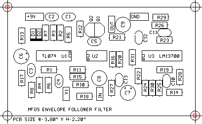
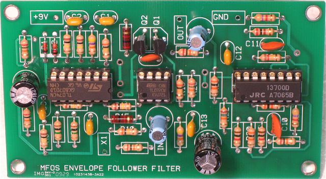
PC Board Details
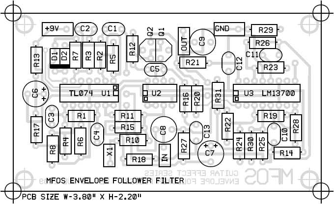
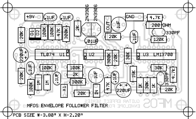
When populating the circuit board start with the IC sockets and then add the resistors. Follow this with any diodes and finally install any remaining components (caps, transistors, etc). The diagrams below show both legends and values. I find the value view nice when I am populating the board and the legend view nice when trouble shooting is necessary.
Resistor Orientation
Resistors can be inserted in either direction.
Capacitor Orientation
Be aware of the markings on aluminum electrolytic and tantalum caps. The positive lead and/or the negative lead will be clearly marked as to which is which. Most of the time brand new caps have the positive lead longer than the other. It is important to orient them correctly or they can be destroyed. Unpolarized aluminum caps will not have any polarity markings and can be inserted in either direction. Film and ceramic type caps do not have any polarity markings and can be inserted in either direction.
Diode, Transistor and IC Orientation
Diodes, transistors and ICs must be oriented correctly. The transistor legend on the PCB is meant to show which direction the transistor is inserted. The transistor's flat side goes even with the legend's flat side and it's curved side goes in the other direction. Diode PCB legends have a heavy line on one side to identify where the cathode goes. Diodes have an obvious cathode marking on them. IC PCB legends clearly indicate the direction the IC should be inserted with both a pin one end and pin one marking. ICs have a notch on the end where pin one is located. A small circle or mark will also be on that end identifying pin 1. IC sockets have a pin one end indicator. Be sure and orient the IC sockets correctly so that when it is time to insert the ICs they will be oriented correctly.
Populating the PCB and Soldering
Install a few components at a time and then trim the leads and solder them. Never trim IC socket leads they are meant to be the correct length already. I usually install components in groups of one value at a time. It is best to trim prior to soldering to avoid applying the shock of trimming to the solder joint. Here is a great video from the people at Curious Inventor about soldering. Curious Inventor's How To Solder VideoDon't use too much solder. Solder joints should be shiny and smooth. If they are gray and lumpy use desoldering braid and try again. Once a solder joint is gray and lumpy don't try to revive it with more solder. It is best to remove the solder and try again.
The correct way to use solder braid is to pull a length (3" or so) out of the container and leave it attached. Hold it by the container so you don't burn your fingers and apply the protruding length of solder braid over the joint you want to desolder. Make sure your iron is wetted (that means it has a coating of solder on it) and then gently press the braid onto the joint with the soldering iron tip. After about a second or two you will see the braid start to suck up solder (turn silver-ish). Remove the iron and braid at the same time and voila the joint should have far less solder on it. Cut off the end of the braid that is saturated with solder before desoldering another joint. Once you get good with braid you will avoid solder suckers which can pull lands completely off of a board.
Envelope Follower Filter PCB Parts Layout (Parts Side Shown) PDF
Envelope Follower Filter PCB Parts Values (Parts Side Shown) PDF
Envelope Follower Filter Populated PCB
This is the board with all of the components soldered on. Notice that I ALWAYS use IC sockets. The parts are inserted from the top or legend side of the board and then trimmed and soldered on the bottom side (as explained above).
Envelope Follower Filter PCB Bottom Copper (Top Side View Shown)
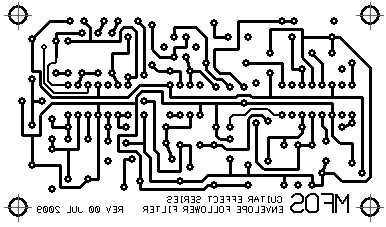
Envelope Follower Filter PCB Top Copper(Top Side View Shown)
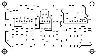
Envelope Follower Filter PCB Top Silk Screen
