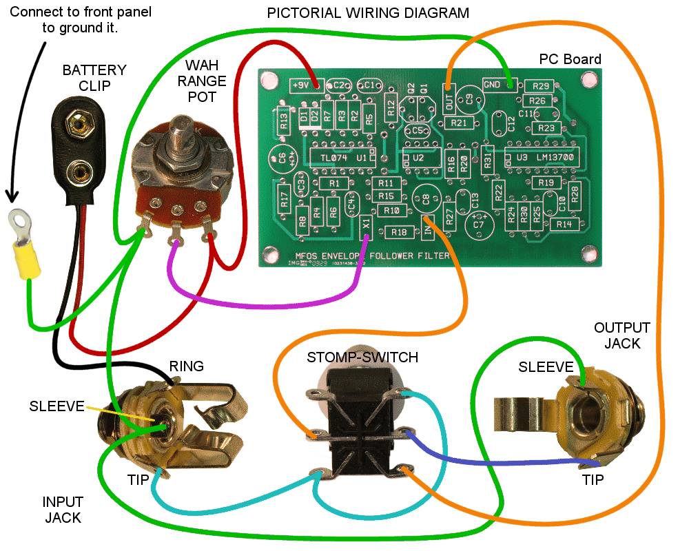
Wiring The Foot PedalI have provided several drawings to help you wire the pedal correctly including a nice pictorial wiring diagram. In this diagram the yellow boxes contain the names of connection points on the PCB where the wires need to be connected. The pictorial diagram below is for the more graphically oriented among us.Click the image at right for a PDF document. Print the pdf (or the image) and as you connect a wire that is shown on the diagram mark is with a highlighter or pen so you can keep track of what is and what is not connected. Wiring errors are by far one of the most common areas where mistakes occur. Take your time, follow the diagram and your effect will work the first time.
|

|
Pictorial Wiring DiagramClick this image to open a larger one. If you print the image in landscape mode you can follow it as you wire your effect.Of course everywhere a wire is connecting to a terminal the wire must be stripped and soldered to the terminal. Solder joints should be shiny and smooth. The rear view of the stomp switch shown may not be the same as yours. Make sure you understand how your stomp switch relates to the switch symbol on the schematic (see stomp switch explanation below). See the schematic page for a complete circuit description of the effect in/out switching operation. |
|
DPDT Stomp Switch StatesHere is a little more explanation on the operation of the DPDT stomp switch. The switch has two states and when you step on the switch you change the state to the other one. It really is that simple.The DPDT stomp switch has two separate single pole double throw switches that are toggled simultaneously as the switch is stomped. As you view the back of the switch shown, for example, each side is a separate single pole double throw switch. Focusing on the right side the top terminal is one switch leg, the bottom terminal is the other switch leg and the middle terminal is the common pole. The left side is the same. The common poles for both switches contact the upper terminals or the lower terminals at the same time depending on the state of the switch. Your stomp switch may look a bit different from this one but it will operate in a similar manner and will most likely have a similar left and right arrangment of the switching elements. Use an ohm meter to become familiar with the operation of your switch and which terminals are which. |

|
Pictures Of The Effect After Wiring
Lastly here are two pictures of the unit after wiring. Click either image for a larger one. The left picture does not show the battery access port or battery holder but the other picture makes clear where it goes after it is installed. Notice that I did not use all of the mounting standoffs. This was to insure that the stomp switch did not contact the switch terminals when the effect was assembled. Notice the self-adhesive feet mounted to the bottom of the foot pedal so that it does not slide around on non-carpeted surfaces.
 |
 |
Here is a good plan of attack for wiring up the effect:
- Before mounting the jacks solder the wires you see in the wiring diagram to them. All of them except the wire that connects the sleeve terminals of the two jacks together should be about 8 inches long.
- Solder the two inch long piece between the jack sleeve terminals.
- Solder the battery clip's black wire to the input jack's "ring" terminal.
- Mount the jacks to the back plate.
- Install R9 and S1 onto the front plate of the foot pedal.
- Attach the wire terminal with the length of wire soldered to it to the front panel.
- Attach the knob to the potentiometer.
- Attach 6" long wires to the populated circuit board at the connection points (+9V, GND, IN, OUT, and X1).
- Mount the circuit board using 3/8" stand-offs and 6-32 nuts and bolts.
- Solder the battery clip's red wire and the wire coming from the PCB +9V circuit point to R9 as shown in the wiring diagram.
- Solder the the wire coming from the input jack's sleeve terminal, the wire coming from the terminal attached to the front panel and the wire coming from the PCB GND circuit point to R9 as shown in the wiring diagram.
- Solder the wire coming from the PCB X1 circuit point to R9 as shown in the wiring diagram.
- Solder the wire coming from the PCB IN circuit point to S1 as shown in the wiring diagram.
- Solder the wire coming from the PCB OUT circuit point to S1 as shown in the wiring diagram.
- Solder the wire coming from the output jack's tip terminal to S1 as shown in the wiring diagram.
- Solder the wire coming from the input jack's tip terminal to S1 as shown in the wiring diagram.
- Solder the wire between the two terminals of S1 as shown in the wiring diagram. Notice that one of the terminals shares a connection with the tip terminal of the input jack.
- Attach a good 9V battery to the battery clip.
- Connect the effect between your instrument and your amplifier.
- Toggle the stomp switch several times and the effect should toggle between the envelope follower filter function and plain guitar.
Success!
If you have gotten to this point and everything is working perfectly then disconnect your guitar and attach the front panel and the battery access port to the case and retest. Still working? You have just succeeded in making your own guitar effect. Congratulations!
Success delayed a little?
If you have gotten to this point and everything is NOT working perfectly then disconnect your guitar. And go over the troubleshooting steps outlined in this link. Trouble shooting measures... Rest assured that once you get everything wired up correctly and are using good ICs and a good battery that the effect will work perfectly. I have followed these exact instructions and I can guarantee that when assembled correctly this effect works really well.