Ray Wilson authored this content while he was actively running MFOS as the founder and resident genius.
We retain the content because it reflects a valuable point of view representing that time and place.
Article by Ray Wilson
I remember when I first heard a fuzz tone. I was about ten years old and my cousin Rick had a really nice Fender guitar and amp and a VOX fuzz tone. He cautiously let me try it and I was mesmerized. The guitar sounded so cool through it and I never thought the day would come when I could build my own. Well the day is here for all of us. Here is a very simple fuzz tone for you to build. You can, of course, lay out a simple PC board for it if you desire to but I used one of my Swiss Op Amp Knife boards. If you build it I hope you have fun with it. Here is more info about the Swiss Op Amp Knife

|
Check the MFOS Fuzz Tone out on YouTube... |
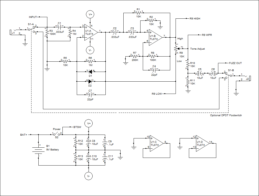
The output of U1-A is fed to one side of the Tone Adjust pot R9 10K linear pot (R9 LOW) and to the input of the high pass filter comprised of U1-B C2 .033uF cap, C3 .033uF cap, R1 10K resistor and R2 10K resistor. Here the .033uF capacitors must be used because they determine the high pass frequency of the high-pass filter. I have to thank Don Lancaster for the filter configuration since it is straight out of "The Active Filter Cookbook" an invaluable resource for synth-diyers. Resistors R8 (100K) and R7 (200K) set the gain of the filter to 1.5 in order to recover a bit of the gain lost through the filter network's differentiator. The 22pF cap is again there to compensate and prevent oscillation. The output of U1-B is connected to the other side of the Tone Adjust pot R9 10K linear pot (R9 HIGH). The high pass filter action of U1-B emphasizes the edges of the squared up waves coming from the "fuzz" generator. By adjusting the pot you can go from a really nice heavy metal fuzz to a fuzz with more high harmonic content. I think of it as giving the fuzz more "edge". You can adjust the Tone Adjust pot between the two extremes to blend the low and high signals to your taste.
The output is attenuated to 1/2 of the output of U1-B so that it is closer to the original signal level. If you do add the DPDT bypass footswitch the volume level won't change too much when you switch between straight through and fuzz tone. The output is coupled from the wiper of R9 to two back to back 10uF caps. This is a sneaky way to get a non-polarized 5uF cap.
This circuit uses the "virtual ground" concept by creating a mid-point between the poles of the battery with R12 and R13 (10K resistors). This mid-point is used as the reference in the circuit (the ground symbols). Op amps U1-C and U1-D are not used. The circuit draws about 7.5mA with the TL074. If you use a LF444CN (low power quad op amp) it only draws about 1.3 mA and works just as well.
Guitar Fuzz Tone

Fuzz Tone Board Details
Fuzz Tone Parts LegendIt is VERY important to place the components on the board EXACTLY as you see them here. If you are an experienced builder you might find that you can change the orientation of some components and eliminate some jumpers. I wanted the layout to look simple and straightforward in case you are just getting started in electronics.

Fuzz Tone Parts Values

Fuzz Tone PC Board Populated
Fuzz Tone PC Board Hookups
Fuzz Tone PC Board Panel
Fuzz Tone Project Parts List
| Qty. | Description | Value | Designators |
|---|---|---|---|
| 1 | TL074 Quad Op Amp | TL074 | U1 |
| 2 | Diode 1N914 | VALUE | D1, D2 |
| 1 | Potentiometer Linear | 10K | R9 |
| 2 | Resistor 1/4 Watt 5% | 100K | R3, R8 |
| 7 | Resistor 1/4 Watt 5% | 10K | R1, R2, R5, R10, R11, R12, R13 |
| 2 | Resistor 1/4 Watt 5% | 1M | R4, R6 |
| 1 | Resistor 1/4 Watt 5% | 200K | R7 |
| 3 | Capacitor Ceramic | .033uF | C1, C2, C3 |
| 2 | Capacitor Ceramic | .1uF | C9, C11 |
| 2 | Capacitor Ceramic | 22pF | C4, C7 |
| 4 | Capacitor Electrolytic | 10uF | C5, C6, C8, C10 |
| 1 | Footswitch DPDT | DPDT | S1 |
| 1 | Switch SPST | SPST | S2 |
| 2 | Jack 1/4" 2 Terminal | . | J1, J2 |
| 1 | Battery | 9V Battery | B1 |


