Ray Wilson authored this content while he was actively running MFOS as the founder and resident genius.
We retain the content because it reflects a valuable point of view representing that time and place.
Article by Ray Wilson
This is an intermediate to advanced project and I do not recommend it as a first project if you are just getting started in synths or electronics. Only the circuit and some explanation are shown here. A lot of project building, troubleshooting and electronics experience is assumed. Additionally, electronic equipment ownership (scope, meters, etc.) is taken for granted. If you are interested in building this project please read the entire page before ordering PC boards to ensure that the information provided is thorough enough for you to complete the project successfully.
Introduction
I like playing synth bass while I play my guitar and this thing is just the ticket. The circuit provides an octave of keys to voltage (1V/Oct) and you could use the little stylus key pattern I include if you just want to make a small one octave stylus keyboard.Circuit Description
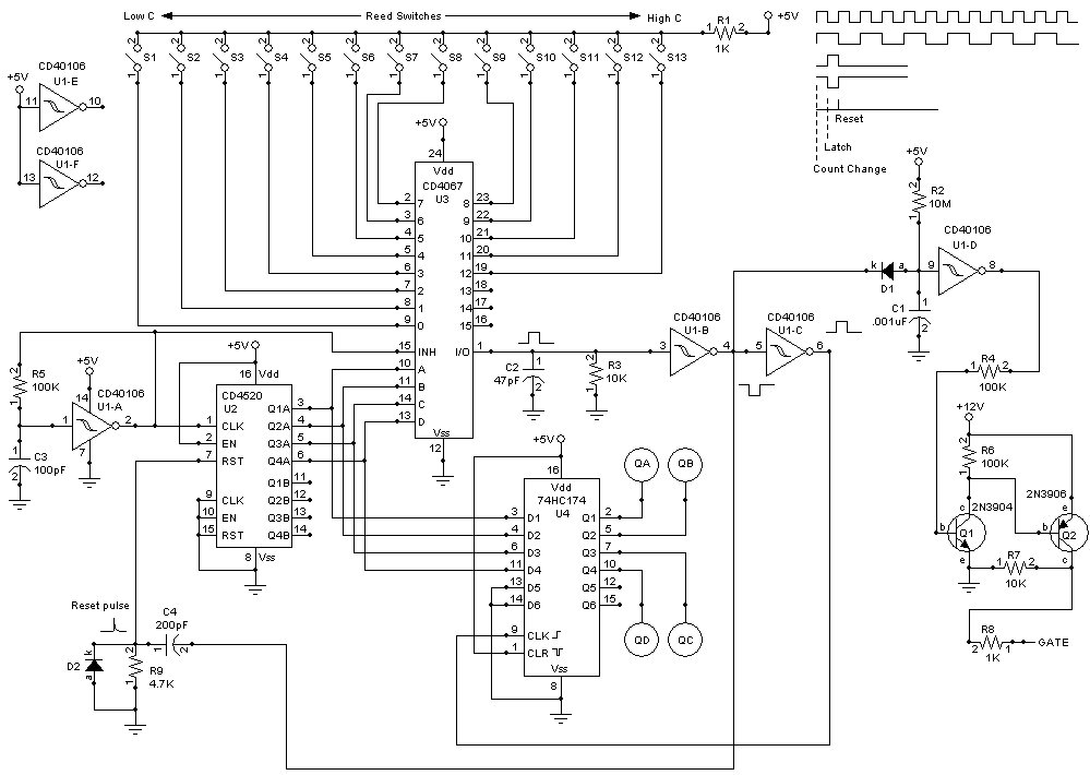
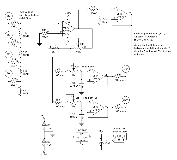
A clock signal is generated by U1-A, R5 and C3 which drives half of U2 the CD4520 dual binary counter. The binary counter outputs (Q1A thru Q4A) cause the key scanner U3 (CD4067 16 channel analog multiplexer) to test for key presses starting from S1 and going up to S13. If no key is pressed the counter continues to count up to 16 but we don't care because the keys are scanned about 6 times every millisecond anyway so unless you have some incredibly fast feet you won't miss a note. When a key is pressed the count on U2 is latched into U4 74HC174 hex flip flop and the counter is reset to 0. The latched count is converted to a voltage by an R/2R ladder which is appropriately scaled by U5-A LF444 quad op-amp, and buffered by the remaining amplifiers. Two of the outputs provide portamento and one is non-portamento. The gate is generated by stretching the series of pulses which appear at U3 pin 1 when a foot-pedal is pressed (or pressed and held). Since the circuit runs on 5 volts the gate is amplified to 12 volts by Q1 and Q2 because my system needs the higher voltage gate. I use the LM78L05 to generate the 5 volts because the circuit draws very little current. The voltage generated by the last key pressed is held until another key is pressed. If two notes are pressed the low note takes priority. This is the perfect sample and hold because there is NO sample cap to slowly discharge.
One Octave Foot Pedal Controller Schematic


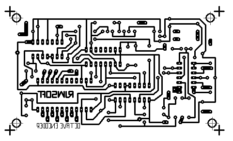
One Octave Foot Pedal Controller PCB Layout

One Octave Foot Pedal Controller Parts Placement

One Octave Foot Pedal Controller Photos


No I did not include all of the sizes I used because you should make it comfortable for you to play but here is the main idea of how the unit is constructed. The black keys have their springs closer to the fulcrum because they are shorter than the white keys and I wanted the pressure to be similar for white and black keys. I used pine for most of the construction. The felt is very important if you don't want to hear a lot of clicking and clacking.

The bolts and nuts are for adjusting the pressure of the keys. You can adjust the white pressure separate from the black pressure. The construction has to be fairly heavy duty because your feet are typically far stronger than your hands. OK.. thank you Mr. Obvious.

I kludged the power supply in because its just easier when you don't have a board ready to go.

A shot of the whole thing with the cover removed. This thing is very cool and I am playing bass lines while I play my guitar. It reminds me of the old band Genesis.

Here is a pattern for a small stylus type keypad. You would hook the keys to the inputs of the CD4067 (the pin 1s of all of the switches) and connect the stylus to pin 1 of R1. Touching the keys with the stylus is just like closing one of the switches shown in the schematic.
