Using Reed Switches and Magnets
Ray Wilson authored this content while he was actively running MFOS as the founder and resident genius.
We retain the content because it reflects a valuable point of view representing that time and place.
Article by Ray Wilson
This is an intermediate to advanced project and I do not recommend it as a first project if you are just getting started in synths or electronics. Only the circuit and some explanation are shown here. A lot of project building, troubleshooting and electronics experience is assumed. Additionally, electronic equipment ownership (scope, meters, etc.) is taken for granted. If you are interested in building this project please read the entire page before ordering PC boards to ensure that the information provided is thorough enough for you to complete the project successfully.
Introduction
A keyboard is a central part of any synthesizer and this is a good keyboard circuit. It is monophonic in function i.e. its a single note keyboard. It performs the function of translating key presses into appropriate voltages so that you get 1V/Octave or .08333 volts per semitone. It also provides gate and trigger signals. The gate goes high when you press any key and remains high until all keys are released. The trigger emits a pulse (approximately 1 to 2 mS) each time a note is pressed or changed. If you play in a legato fashion in which a key is always pressed the trigger pulses will still occur any time a new note is played whereas the gate will stay high until all keys are released.The keyboard needs electronic switches and I decided to use reed switches which are activated by placing a magnet near them. Quite a while back Scott Stites fired my imagination when he mentioned that he was thinking of making a reed switch based keyboard. You could use this circuit with any type of switch you don't have to use reed switches. The reeds (paddles) of a reed switch are made of a magnetic alloy and are oriented so that they are very near to one another. When the reed switch is placed into a magnetic field the paddles become magnetized, attract one another and close. When the magnet is removed the paddles are no longer magnetized and re-open. Reed switches display a property known as hysteresis. When you move a magnet toward the reed switch it closes at distance A. To deactivate the reed switch you remove the magnet. As you do so you will notice that you must bring it further away from the reed switch than distance A to get it to open. The difference in distance is called the hysteresis zone. The reed switches were inexpensive, have gold plated contacts, are sealed against moisture and dirt, and are very quiet... the perfect keyboard switch.
For keys I used an old organ keyboard which contained wooden piano like key sets (two very well preserved sets: 37 note and 51 note). I first constructed a case to hold the keyboard and then I added springs to the keys to pull them back home after pressing them. When I do this again (for the 51 note keyboard) I plan to use opposing magnets instead of springs to push the keys back home. The magnets are mounted on the keys and the reed switches are stationary. As a key is pressed its magnet is moved close to its corresponding stationary reed switch and the switch closes. When the key is released the magnet is moved away and the reed switch opens. I found that I had quite enough travel to get the switch to close and open including getting out of the hysteresis zone.
The switches close very near the end of the key press and open with room to spare for the key to fall back home. I had to experiment with where to place the magnets on the keys. When I had all of the magnets right next to one another I noticed that there was interaction between adjacent reed switches and magnets. If a key was pressed and then its adjacent key was pressed the original key's switch would remain activated until I released the adjacent key. I solved this by staggering the magnets as you can see in the illustrations below (a suggestion from fellow synth-diy'er Scott Stites).
I also noticed that the relative orientation of the magnet and reed switch is very important. The reed switches are more sensitive to the magnet when the magnet is placed closer to either end of the reed switch. At a certain distance from the end I was unable to get out of the hysteresis zone in the available space. So I had to move the reed switch so that the magnet was nearer the middle of the reed switch. If you go too far (magnet in the middle of the reed switch) the reed switch sensitivity is too low and it won't close even at full key press. I had to adjust the placement of each reed switch on the plexiglas platform I made for them above the keys and magnets. I used a silicon sealer to mount the reeds. I used a small dab at first during placement but once I had them in good position I went back and slathered more on to hold them firmly in place.
Lets go over the electronics used for the keyboard.
Matrix 1V/Octave Keyboard Controller Schematic Page 1
This is the switch matrix. As you can see there are rows (R0-R4) and columns (C0-C7). The columns are brought to a high logic level sequentially by the outputs of U1 CD4051 (8 Channel CMOS
Analog Multiplexer). Its common in/out pin is tied to 5V through a 1K resistor. Its A,B, and C channel select logic lines are controlled by Q2A, Q3A, and Q4A of U2 CD4520 Dual Binary Up Counter (which
is wired as an 8 bit counter). Notice that we are not using Q1A as the lowest bit but Q2A instead. When contemplating this circuit just look at bit Q2A as the lowest bit of a six bit binary counter
consisting of Q2A=1s Q3A=2s Q4A=4s Q1B=8s Q2B=16s Q3B=32s. The rows are connected to I/O-0 through I/O-4 of U3 another CD4051 (8 Channel CMOS Analog Multiplexer). U3 is used to test for the presence
of a high logic level on a row. Here is what happens. The counter and the Analog Multiplexers are set up so that each row listens while all 8 columns are activated one at a time.
R0 sits and listens while columns C0, C1, C2, C3, C4, C5, C6, C7 are sequentially activated.
R1 sits and listens while columns C0, C1, C2, C3, C4, C5, C6, C7 are sequentially activated.
R2 sits and listens while columns C0, C1, C2, C3, C4, C5, C6, C7 are sequentially activated.
R3 sits and listens while columns C0, C1, C2, C3, C4, C5, C6, C7 are sequentially activated.
R4 sits and listens while columns C0, C1, C2, C3, C4, C5, C6, C7 are sequentially activated.
R5 through R7 listen but they are not used for the 37 keys encoded.
This cycle continually repeats thus the term matrix scanning encoder. The low order bits of the counter (Q2A, Q3A, and Q4A) are used to sequence the columns and the higher order bits (Q1B, Q2B, and
Q3B) are used to sequence the rows. The switch matrix shown only encodes 37 keys but the encoding circuit can scan and encode up to 64 keys.
Matrix 1V/Octave Keyboard Controller Schematic Page 2
When no switches are pressed the circuit just scans the matrix waiting for a key to be pressed. The clock signal generated by U4A (inverting schmitt trigger), R3 and C2 drives the 8 bit counter made up of the two sections of U2 (note that Q4A drives the enable line of the second counter causing it to clock appropriately). The clock period is about R*C or 10uS (or 100 KHz) As stated above we use Q2A=1s Q3A=2s Q4A=4s Q1B=8s Q2B=16s Q3B=32s as our six bit binary counter.
The counter outputs are controlling the I/Os of the 4051 8 Channel CMOS Analog Multiplexers. So as our six bits count from 0 to 7 we sequentially drive all 8 columns and test row 0. As we count from 8 to 15 we sequentially drive all 8 columns and test row 1. Can you guess what happens next? As we count from 16 to 23 we sequentially drive all 8 columns and test row 2. And so on until we have sequenced through all columns for each row.
When a key is pressed closing a switch (S10 for example) nothing happens when we sequentially drive the columns and test row 0 but as we drive the columns and test row 1 something happens when column 1 is driven. Row 1 goes HIGH. The high from row 1 is fed through U3 pin 14 to U3 pin 3, is dropped across R9 and subsequently drives pin 11 of U4-E high which causes its output (U4-E pin 10) to go low. This low level is fed to U4-D pin 9 after a very slight delay caused by R8 and C6 which causes its output (U4-D pin 8) to go high. The rising edge of this high pulse causes the counter's output to be latched into U5 which stores the count. The rising edge of the low going pulse that occurred at the output of U4-E is used to reset the counter to 0. This reset action causes the encoder to catch the first key down it encounters and immediately start scanning from 0 again. This gives the encoder low note priority. C5 is used to clean up any stray spikes appearing at U3 pin 3 while the encoder is scanning.
When a key is pressed and held the pulses continue to appear at U3 pin 3 at the appropriate count and the inverted pulses appearing at U4-E pin 10 continue as well. These low going pulses are fed to the cathode of D2 and thus continually keep C3 discharged so that the input of U4-F pin 13 sees a low level driving its output high. When all keys are released and the pulses stop R1 charges C3 causing U4-F's output to go low. This signal is used to generate the keyboard's gate signal. The rising edge of U4-F's output is fed to point GG via C1 and D1. This signal is used to generate a trigger when a key is initially pressed or repeatedly pressed and released.
Matrix 1V/Octave Keyboard Controller Schematic Page 3
The outputs of the latch are fed to a group of XOR gates and to the R/2R ladder used to convert the digital count to a corresponding and proportional analog voltage. Notice that each XOR gate has the logic level from one of the counter bits fed to its inputs. One input is directly connected but the other input is connected via a 1 Meg resistor. Additionally each of the inputs with the resistor has a cap to ground. Here is what is happening. XOR gates only go high when there is a different logic level on each input. When both inputs are high the output is low when both inputs are low the output is low, otherwise the output is high. What we are doing is delaying a change in logic level to one of the inputs so that there is a momentary difference between the inputs any time the logic level for any counter output changes. When circuit point Q5 goes high for example pin 1 of U6-A goes high immediately but cap C7 has to charge from the previous low logic level to the new level via R11 and that takes several hundred microseconds. During the time that the inputs are different the output U6-A pin 3 goes high. When C7 charges to the new logic level the output U6-A pin 3 goes low again. We capture the positive excursion of the pulses from any of the XOR gates on C16 (via D4 through D9) which then discharges through R35. The voltage appearing on C16 is presented to U8-A pin 1 (inverting schmitt trigger input) whose output is inverted by U8-B whose output in turn is used to generate the trigger signal for the keyboard. This is how we generate the keyboard trigger signal any time you change notes. And remember GG from above well she makes an appearance here so that the initial press of a key also causes a trigger. That way we get triggers even when we are pressing the same key again and again (thus not causing a change in the count).
The R/2R ladder magically converts the count latch output (U5 74HC374) to a voltage level directly proportional to the latched count. (Slightly better explanation) Since we are powering the logic chips with a LM78L05 the voltage steps are not high enough so we add a smidgen of gain and then some followers (with lag or portamento controls) to get the voltage to the outputs of the keyboard as 1V/Octave or .08333 volts per half step. The voltage output of the LM78L05 will be regulated and stable but it will probably not be exactly 5 volts so you need to trim the gain via pot R15. The values shown should handle the full variation you might see in any LM78L05.
Matrix 1V/Octave Keyboard Controller Schematic Page 4
My system being +/-12V, I convert the gate and trigger signals to ground to +12V levels with the boosters shown below.
Matrix 1V/Octave Keyboard Controller Reed Switch and Diode Diagram
If you find the schematic view of the key matrix a bit confusing this friendlier diagram might help you to understand it.
Matrix 1V/Octave Keyboard Controller PCB Layout (Parts Side Shown)
Matrix 1V/Octave Keyboard Controller Parts Layout
Notice that in addition to the plethora of jumpers you need to run two wires on the board. Connect RST to RST and connect GG to GG. If I get these manufactured someday I will get them double sided and eliminate all of the jumpers and these two wires.
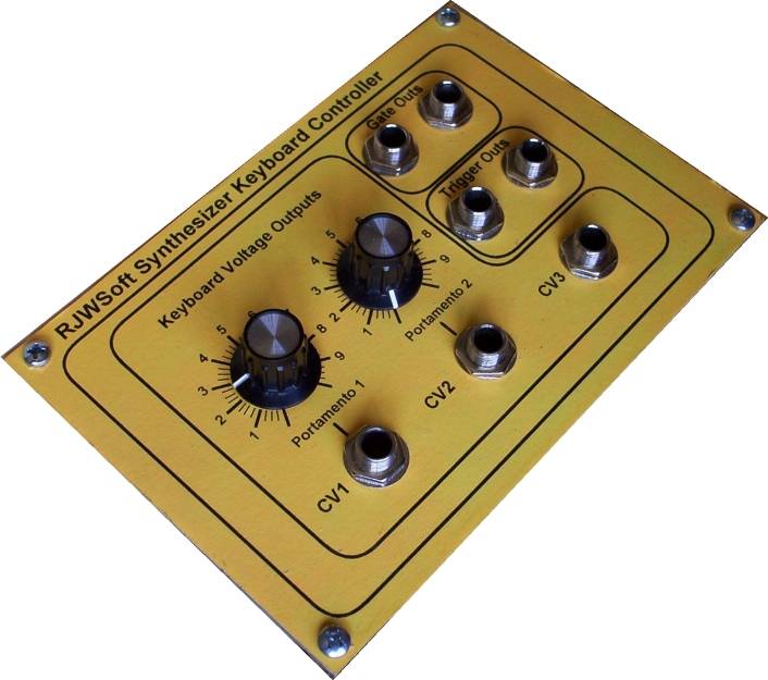
Matrix 1V/Octave Keyboard Controller Face Plate
Click for a PDF of this layout.
Stable Reed Switch Mounting Is Important
It is important for the stationary reed switches to be solidly stationary. The 1/10" thick plexiglas platform is mounted to a very rigid aluminum "L" channel on both sides and the "L" channels are solidly mounted to the keyboard case with 1/4" bolts. I used some fairly stiff compression springs between the "L" channel and the case to help me get the platform to optimum height above the key mounted magnets. The magnets are firmly stuck to the keys with Scotch brand double stick foam tape. On the next keyboard I plan to use a good two-part epoxy but the tape is working so far and I soundly pound the keys some times. The switches were hand placed (with a dot of silicon sealer) while I worked the key to get the optimum close/open position. It was a little tedious but it built character. After I had all of the switches placed I glued the snot out of them (as you can see). Then I attached the diodes and some extension wires and essentially wired the matrix (Of course I said hello to Neo while visiting). Next time I will attach the diodes and extension wires before I mount the switches. I used ribbon cable wire to wire the matrix. Its color coding, stranded flexibility and coolness all played a part in the decision.
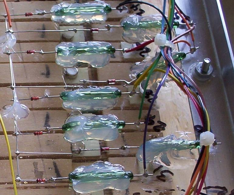
Reed Switches and Diodes Kludged and Final Glue Applied
A gooey closeup of the reed switches after the final "gluing" with clear GE brand silicon sealer.
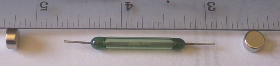
Reed Switches and Magnets Showing Relative Sizes Used
This should help you to see the relative sizes of the reed switches and the magnets I used. These are powerful little magnets too. I got them from Amazing Magnets. I got the reed switches from HOSFELT Electronics.
HOSFELT PART: 51-206 Reed Switch
Amazing Magnets Part: D125B-0050 0.250" Dia x 0.125" Thick NdFeB Disc Magnet, Grade N40, Ni Plated with Matte finish, Axially Magnetized
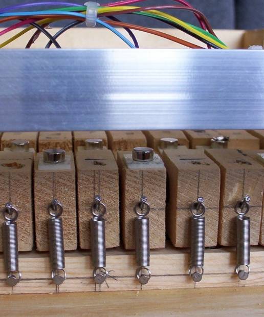
Staggered Magnet Placement and Key Return Springs
Notice the staggering of the magnets to solve the problem of intra key interaction. I got these springs from American Science & Surplus they are very supple. Next time I plan to use opposing magnets instead at the front of the keyboard to push the keys home instead of pulling them with springs. I think that the mounting and the whole bit will be less tedious than this spring thing was.
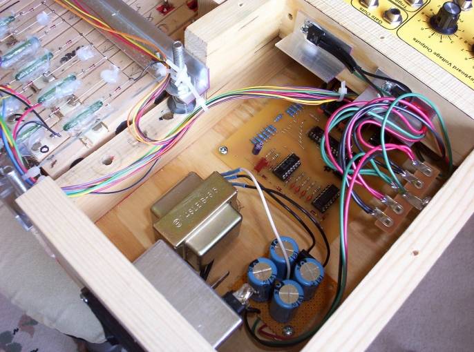
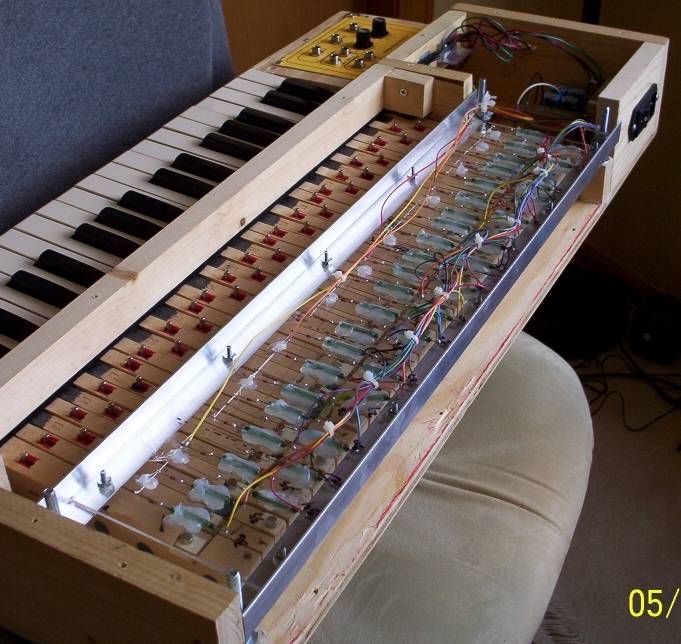
The Keyboard Electronics and Kludged Power Supply
I kludged up the power supply and mounted the controller and voila this keyboard works extremely well. I am very happy with its performance. It is far more stable than the analog keyboard I built. I have to say that if I used these switches with the former design I would expect it to be a lot more stable and reliable because I used some really crappy switches on my old one.