Ray Wilson authored this content while he was actively running MFOS as the founder and resident genius.
We retain the content because it reflects a valuable point of view representing that time and place.
Article by Ray Wilson
This is an intermediate to advanced project and I do not recommend it as a first project if you are just getting started in synths or electronics. Only the circuit and some explanation are shown here. A lot of project building, troubleshooting and electronics experience is assumed. Additionally, electronic equipment ownership (scope, meters, etc.) is taken for granted. If you are interested in building this project please read the entire page before ordering PC boards to ensure that the information provided is thorough enough for you to complete the project successfully.
Introduction
A keyboard is a central part of any synthesizer and this is a good keyboard circuit. It is monophonic in function i.e. its a single note keyboard. It performs the function of translating key presses into appropriate voltages so that you get 1V/Octave or .08333 volts per semitone. It also provides sampled and held voltage as well as gate and trigger signals. The gate goes high when you press any key and remains high until all keys are released. The trigger emits a pulse (approximately 1 to 2 mS) each time a note is pressed or changed. If you play in a legato fashion in which a key is always pressed the trigger pulses will still occur any time a new note is played whereas the gate will stay high until all keys are released. The keyboard needs electronic switches which can be wired into the necessary matrix shown later in this article.In another article I show how reed switches and magnets can be used to turn an old piano keyboard into a synthesizer keyboard. This circuit is the same as the one shown there with a few
improvements and a new PCB layout.
Reed Switch Keyboard
Matrix Scanning 1V/Octave Keyboard Page 1 PDF
| When no switches are pressed the circuit just scans the matrix waiting for a key to be pressed. The clock signal generated by U4A (inverting schmitt trigger), R3 and C2 drives the 8 bit
counter made up of the two sections of U2 (note that Q4A drives the enable line of the second counter causing it to clock appropriately). The clock period is about R*C or 10uS (or 100 KHz) We use
Q2A=1s Q3A=2s Q4A=4s Q1B=8s Q2B=16s Q3B=32s as our six bit binary counter.
The counter outputs are controlling the I/Os of the 4051 8 Channel CMOS Analog Multiplexers. So as our six bits count from 0 to 7 we sequentially drive all 8 columns and test row 0. As we count from 8 to 15 we sequentially drive all 8 columns and test row 1. Can you guess what happens next? As we count from 16 to 23 we sequentially drive all 8 columns and test row 2. An so on until we have sequenced through all columns for each row. When a key is pressed closing a switch (S10 for example) nothing happens when we sequentially drive the columns and test row 0 but as we drive the columns and test row 1 something happens when column 1 is driven. Row 1 goes HIGH. The high from row 1 is fed through U3 pin 14 to U3 pin 3, is dropped across R9 and subsequently drives pin 11 of U4-E high which causes its output (U4-E pin 10) to go low. This low level is fed to U4-D pin 9 which causes its output (U4-D pin 8) to go high. The rising edge of this high pulse causes the counter's output to be latched into U5 which stores the count. The rising edge of the low going pulse that occurred at the output of U4-E is used to reset the counter to 0. This reset action causes the encoder to catch the first key down it encounters and immediately start scanning from 0 again. This gives the encoder low note priority. C5 is used to clean up any stray spikes appearing at U3 pin 3 while the encoder is scanning. When a key is pressed and held the pulses continue to appear at U3 pin 3 at the appropriate count and the inverted pulses appearing at U4-E pin 10 continue as well. These low going pulses are fed to the cathode of D2 and thus continually keep C3 discharged so that the input of U4-F pin 13 sees a low level driving its output high. When all keys are released and the pulses stop R1 charges C3 causing U4-F's output to go low. This signal is used to generate the keyboard's gate signal. The rising edge of U4-F's output is fed to point GG via C1 and D1. This signal is used to generate a trigger when a key is initially pressed or repeatedly pressed and released. |
Matrix Scanning 1V/Octave Keyboard Page 2 PDF
| The outputs of the latch are fed to a group of XOR gates and to the R/2R ladder used to convert the digital count to a corresponding and proportional analog voltage. Notice that each XOR
gate has the logic level from one of the counter bits fed to its inputs. One input is directly connected but the other input is connected via a 1 Meg resistor. Additionally each of the inputs with
the resistor has a cap to ground. Here is what is happening. XOR gates only go high when there is a different logic level on each input. When both inputs are high the output is low when both inputs
are low the output is low, otherwise the output is high. What we are doing is delaying a change in logic level to one of the inputs so that there is a momentary difference between the inputs any
time the logic level for any counter output changes. When circuit point Q5 goes high for example pin 1 of U6-A goes high immediately but cap C7 has to charge from the previous low logic level to the
new level via R11 and that takes several hundred microseconds. During the time that the inputs are different the output U6-A pin 3 goes high. When C7 charges to the new logic level the output U6-A
pin 3 goes low again. We capture the positive excursion of the pulses from any of the XOR gates on C16 (via D4 through D9) which then discharges through R35. The voltage appearing on C16 is
presented to U8-A pin 1 (inverting schmitt trigger input) whose output is inverted by U8-B whose output in turn is used to generate the trigger signal for the keyboard. This is how we generate the
keyboard trigger signal any time you change notes. And remember GG from above well she makes an appearance here so that the initial press of a key also causes a trigger. That way we get triggers
even when we are pressing the same key again and again (thus not causing a change in the count).
The R/2R ladder magically converts the count latch output (U5 74HC374) to a voltage level directly proportional to the latched count. (Slightly better explanation) Since we are powering the logic chips with a LM78L05 the voltage steps are not high enough so we add a smidgen of gain and then some followers (with lag or portamento controls) to get the voltage to the outputs of the keyboard as 1V/Octave or .08333 volts per half step. The voltage output of the LM78L05 will be regulated and stable but it will probably not be exactly 5 volts so you need to trim the gain via pot R15. The values shown should handle the full variation you might see in any LM78L05. I suggest that you buy more of the metal film 499K and 1M 1% resistors than you need and hand match them to find R and 2R as accurately as possible. They are very handy to have on hand anyway. |
Matrix Scanning 1V/Octave Keyboard Page 3 PDF
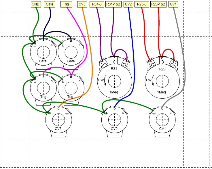
| These are the gate and trigger level shifters. Gate and Trigger outputs go from Ground to +12V. |
Matrix Scanning 1V/Octave Keyboard Page 4 PDF
| The switch matrix is shown above. As you can see there are rows (R0-R4) and columns (C0-C7). The columns are brought to a high logic level sequentially by the outputs of U1 CD4051 (8
Channel CMOS Analog Multiplexer). Its common in/out pin is tied to 5V through a 1K resistor. Its A,B, and C channel select logic lines are controlled by Q2A, Q3A, and Q4A of U2 CD4520 Dual Binary Up
Counter (which is wired as an 8 bit counter). Notice that we are not using Q1A as the lowest bit but Q2A instead. When contemplating this circuit just look at bit Q2A as the lowest bit of a six bit
binary counter consisting of Q2A=1s Q3A=2s Q4A=4s Q1B=8s Q2B=16s Q3B=32s. The rows are connected to I/O-0 through I/O-4 of U3 another CD4051 (8 Channel CMOS Analog Multiplexer). U3 is used to test
for the presence of a high logic level on a row. Here is what happens. The counter and the Analog Multiplexers are set up so that each row listens while all 8 columns are activated one at a time. R0 sits and listens while columns C0, C1, C2, C3, C4, C5, C6, C7 are sequentially activated. R1 sits and listens while columns C0, C1, C2, C3, C4, C5, C6, C7 are sequentially activated. R2 sits and listens while columns C0, C1, C2, C3, C4, C5, C6, C7 are sequentially activated. R3 sits and listens while columns C0, C1, C2, C3, C4, C5, C6, C7 are sequentially activated. R4 sits and listens while columns C0, C1, C2, C3, C4, C5, C6, C7 are sequentially activated. R5 through R7 listen but they are not used for the 37 keys encoded. This cycle continually repeats thus the term matrix scanning encoder. The low order bits of the counter (Q2A, Q3A, and Q4A) are used to sequence the columns and the higher order bits (Q1B, Q2B, and Q3B) are used to sequence the rows. The switch matrix shown only encodes 37 keys but the encoding circuit can scan and encode up to 64 keys (8 columns x 8 rows). |
Matrix Scanning 1V/Octave Keyboard PCB Parts Layout (Parts Side Shown) PDF
Matrix Scanning 1V/Octave Keyboard PCB Bottom Copper (Parts Side Shown)
Matrix Scanning 1V/Octave Keyboard PCB Top Copper(Parts Side Shown)
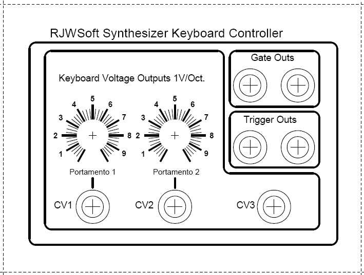
Matrix Scanning 1V/Octave Keyboard PCB Front Panel (Parts Side Shown) PDF
Matrix Scanning 1V/Octave Keyboard PCB Back Panel (Parts Side Shown) PDF
Matrix Scanning 1V/Octave Keyboard Project Parts List
| Qty. | Description | Value | Designators |
|---|---|---|---|
| 2 | 2N3904(s) | 2N3904 | Q1, Q3 |
| 2 | 2N3906(s) | 2N3906 | Q2, Q4 |
| 1 | 74HC374 Octal D Flip Flop | 74HC374 | U5 |
| 2 | CD40106(s) | CD40106 | U4, U8 |
| 2 | CD4051 8 Chan Mux/Demux(s) | CD4051 | U3, U1 |
| 2 | CD4070 Quad XOR(s) | CD4070 | U6, U7 |
| 1 | CD4520 Dual Binary Counter | CD4520 | U2 |
| 2 | Ceramic Capacitor (S)(s) | .001uF | C3, C16 |
| 1 | Ceramic Capacitor (S) | .01uF | C1 |
| 2 | Ceramic Capacitor (S)(s) | 0.22uF | C11, C14 |
| 7 | Ceramic Capacitor (S)(s) | 100pF | C2, C7, C8, C9, C10, C15, C12 |
| 1 | Ceramic Capacitor (S) | 200pF | C4 |
| 1 | Ceramic Capacitor (S) | 47pF | C5 |
| 1 | Cermet trimmer | 20K | R15 |
| 3 | Electrolytic Capacitor(s) | 10uF | C17, C13, C18 |
| 9 | High Speed Sw. Diode(s) | 1N914, 1N4148 | D3, D2, D1, D4, D6, D7, D8, D9, D5 |
| 37 | Keyboard Switches for keyboard |
SPST | S1, S9, S10, S11, S12, S13, S14, S15, S16, S17, S18, S19, S20, S21, S22, S23, S24, S31, S32, S33, S34, S35, S36, S37, S2, S3, S4, S5, S6, S7, S8, S25, S26, S27, S28, S29, S30 |
| 1 | LF444 Quad Op Amp | LF444 | U9 |
| 1 | LM78L05 5V Reg. | LM78L05 | U10 |
| 2 | Potentiometer(s) | 1M | R23, R31 |
| 2 | Resistor 1/4 Watt 1% Metal film(s) | 100 ohm | R22, R30 |
| 3 | Resistor 1/4 Watt 1% Metal film(s) | 100 ohms | R39, R25, R32 |
| 3 | Resistor 1/4 Watt 1% Metal film(s) | 100K | R37, R40, R43 |
| 4 | Resistor 1/4 Watt 1% Metal film(s) | 10K | R42, R41, R44, R45 |
| 1 | Resistor 1/4 Watt 1% Metal film | 1K | R38 |
| 7 | Resistor 1/4 Watt 1% Metal film(s) | 1M | R13, R17, R19, R24, R27, R34, R36 |
| 5 | Resistor 1/4 Watt 1% Metal film(s) | 499K | R14, R18, R21, R26, R29 |
| 1 | Resistor 1/4 Watt 5% | 100K | R3 |
| 1 | Resistor 1/4 Watt 5% | 10K | R9 |
| 1 | Resistor 1/4 Watt 5% | 10M | R1 |
| 3 | Resistor 1/4 Watt 5%(s) | 1K | R5, R10, R4 |
| 6 | Resistor 1/4 Watt 5%(s) | 1M | R11, R12, R20, R33, R28, R16 |
| 1 | Resistor 1/4 Watt 5% | 3M | R35 |
| 1 | Resistor 1/4 Watt 5% | 4.7K | R7 |
| 2 | Resistor 1/4 Watt 5%(s) | 47K | R6, R2 |
| 37 | High Speed Sw. Diode(s) for keyboard |
1N914, 1N4148 | D1, D3, D4, D5, D7, D11, D12, D13, D14, D15, D16, D17, D18, D20, D22, D23, D24, D25, D26, D28, D30, D31, D32, D33, D34, D35, D36, D37, D8, D2, D6, D9, D10, D19, D21, D27, D29 |
Miscellaneous
- (1) 4" x 5" 1/16" thick Aluminum plate for mounting the pots and switches.
- 1 Keyboard with 1 single pole switch per key or keys that close to a bus that can be divided into sections as necessary.
- One Case to hold the unit (homemade wooden case).
- Assorted hardware 1" 6-32 nuts and bolts, 1/2" #8 wood screws, etc
- Knobs for potentiometers, wire, solder and typical assorted electronics hand tools.
- Digital Volt Meter and a Signal Tracer or oscilloscope for testing.