Ray Wilson authored this content while he was actively running MFOS as the founder and resident genius.
We retain the content because it reflects a valuable point of view representing that time and place.
Article by Ray Wilson
This is an intermediate to advanced project and I do not recommend it as a first project if you are just getting started in synths or electronics. Only the circuit and some explanation are shown here. A lot of project building, troubleshooting and electronics experience is assumed. Additionally, electronic equipment ownership (scope, meters, etc.) is taken for granted. If you are interested in building this project please read the entire page before ordering PC boards to ensure that the information provided is thorough enough for you to complete the project successfully.
Introduction
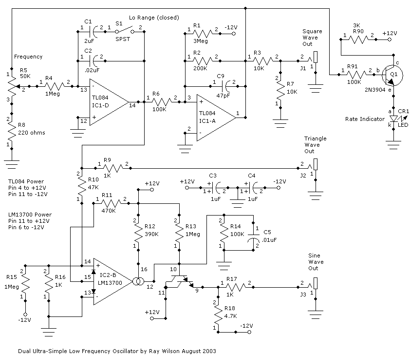
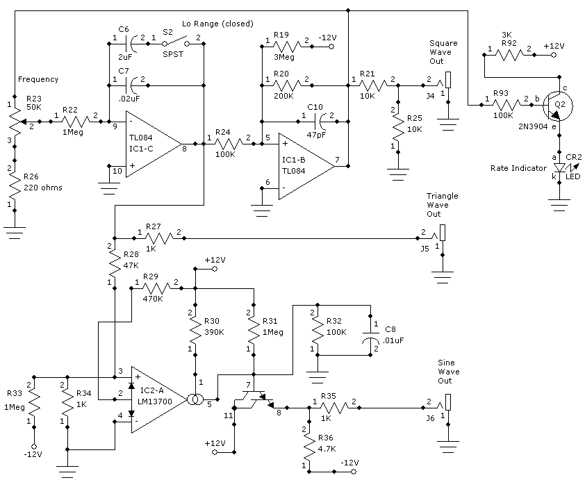
I am finding that the ambient electronic music I am creating is requiring lots of LFOs. Here is a really simple yet very useful Sine, Triangle and Square Wave LFO. In low range this thing will take minutes to cycle when turned all the way down. I put the rate indicators on as an afterthought, thus the whacky resistor numbers. The reason this is dual is because I couldn't stand leaving a perfectly good half of a LM13700 sitting idle.Circuit Description
The theory of the oscillator is the same as the Super Simple Ramp LFO except as you can see there is no diode and 1K resistor to yank the inverting input of IC1-D around so the integrator's output goes up and down at the same rate. The LM13700 provides sine shaping. I plan to try to use the second LM13700 to provide voltage control by essentially replacing R4 with one wired as a voltage controlled tranconductance amp.
Dual Sine, Triangle, and Square Wave LFO


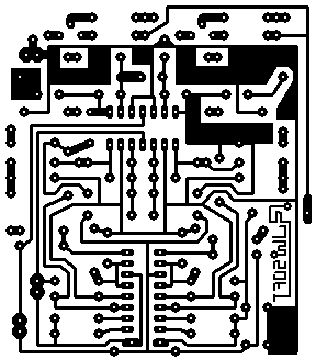
Dual Sine, Triangle, and Square Wave LFO PCB Layout (Component Side View)

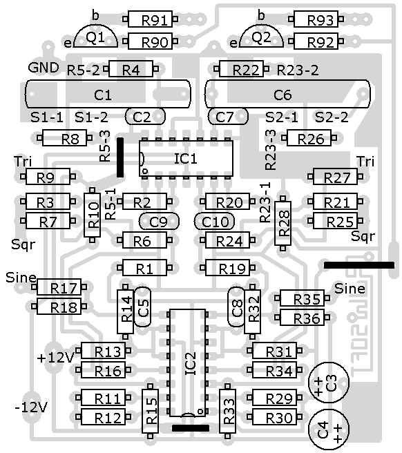
Dual Sine, Triangle, and Square Wave LFO Parts Placement

Dual Sine, Triangle, and Square Wave LFO Parts List (Thanks to Colin Raffel)
| Qty | Description | Value | Name |
| 2 | Resistor, 1/4 Watt | 3M | R1, R19 |
| 2 | Resistor, 1/4 Watt | 200k | R2, R20 |
| 4 | Resistor, 1/4 Watt | 10k | R3, R7, R21, R25 |
| 6 | Resistor, 1/4 Watt | 1M | R4, R13, R15, R22, R31, R33 |
| 2 | Pot, Linear | 50k | R5, R23 |
| 6 | Resistor, 1/4 Watt | 100k | R6, R14, R24, R32, R91, R93 |
| 2 | Resistor, 1/4 Watt | 220ohm | R8, R26 |
| 6 | Resistor, 1/4 Watt | 1k | R9, R16, R17, R27, R34, R35 |
| 2 | Resistor, 1/4 Watt | 47k | R10, R28 |
| 2 | Resistor, 1/4 Watt | 470k | R11, R29 |
| 2 | Resistor, 1/4 Watt | 390k | R12, R30 |
| 2 | Resistor, 1/4 Watt | 4.7k | R18, R36 |
| 2 | Resistor, 1/4 Watt | 3k | R90, R92 |
| 2 | Nonpolar Cap | 2uF | C1, C6 |
| 2 | Nonpolar Cap | .02uF | C2, C7 |
| 2 | Polarized Cap | 1uF | C3, C4 |
| 2 | Nonpolar Cap | .01uf | C5, C8 |
| 2 | Nonpolar Cap | 47pF | C9, C10 |
| 1 | Quad Op Amp | TL084 | IC1 |
| 1 | Dual OTA | LM13700 | IC2 |
| 2 | Transistor | 2n3904 | Q1, Q2 |
| 2 | LED | None | CR1, CR2 |
| 2 | Toggle Switch | SPST | S1, S2 |