Ray Wilson authored this content while he was actively running MFOS as the founder and resident genius.
We retain the content because it reflects a valuable point of view representing that time and place.
Article by Ray Wilson
This is an intermediate to advanced project and I do not recommend it as a first project if you are just getting started in synths or electronics. Only the circuit and some explanation are shown here. A lot of project building, troubleshooting and electronics experience is assumed. Additionally, electronic equipment ownership (scope, meters, etc.) is taken for granted. If you are interested in building this project please read the entire page before ordering PC boards to ensure that the information provided is thorough enough for you to complete the project successfully.
Introduction
All the noise you could want AND MORE. This circuit provides: White Noise, Digital Noise, Roaring Noise, Grainy Noise, AND... Random Gates and Triggers.Circuit Description
Q2 is a small signal NPN transistor (2N2712 or 2N3904 selected for best noise). R1 limits the current through the reversed biased e-b junction but since the voltage drop across it is 24 volts the junction breaks down and makes noise. The white noise that is developed across the e-b junction is capacitively coupled into OP-Amp IC1-B where a gain of between 470 to as much as you want is applied. You need to insure that the level of noise at pin 7 of IC1-B is about 5 to 6 volts AVERAGE and 8 to 9 volts MAXIMUM PEAK to PEAK. By doing that everything else should work. IC1-A is used as a comparator comparing the average value of the noise to the noise itself. This results in rail to rail noise appearing at pin 1 of iC1-A. You can square the digital noise up a bit by adding a small (i.e. 5 to 10 pF) cap between IC1 pins 1 and 3. This noise is buffered and filtered a bit by IC2-A. IC2-A's output sounds like Niagra Falls. IC1-B's output is buffered and gained up a bit by IC1-C. The output of IC1-C is fed into the window comparator made up by IC1-D, IC2-C and associated components. R20 adjusts the window. When the noise appearing on IC1-D is higher than the voltage applied to its pin 13 then IC1-D's output goes high. When the noise appearing on IC2-C is lower than the voltage applied to its pin 9 then IC2-C's output goes low. Diodes CR4 and CR5 pass the high excursions of IC1-D and the low excursions of IC2-C and drop them on R23. By adjusting R20 you can go from a few clicks to roaring noise appearing at the output of IC2-D. The high excursions of IC1-D are also fed via CR2 to the clock input of IC3-A (D Flip Flop). The two flip flops are wired so that they form a divide by four counter. Thus the random clocks appearing at pin 3 of IC3-A cause pin 13 of IC3-B to go high and low randomly (i.e. without a regular frequency). These high and low excursions are fed out as Random Gates and the front end of the gate pulses is sent out over the Trigger output. The Graininess control (window comparator range adjuster) affects the output of gates and triggers. When the Grainy noise output is hardly clicking you will get slow random gates and triggers. When the Grainy noise sounds like a downpour then you will get fast random gates and triggers. When the gates or triggers are occuring fast enough they sound like noise (again). I used LF444s on my board which are a lower current direct replacement for the TL084s.For the reversed biased e-b junction you can try any old small signal NPN you have lying around but the 2N3904 or 2N2712 will definitely work.
YOU WILL DEFINITELY WANT TO ADD VOLTAGE DIVIDING POTS FOR THE OUTPUTS. They are pretty beefy (+ and - 10 to 12 volts).
There you have it now go have some random fun.
Multi Noise and Random Gate/Trigger Generator Schematic
Multi Noise and Random Gate/Trigger Generator PCB (Parts Side Shown)
Multi Noise and Random Gate/Trigger Generator Parts Placement
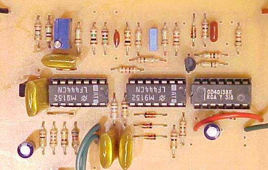
Notice that the ICs DON'T all face the same way! |
Multi Noise and Random Gate/Trigger Generator Photo
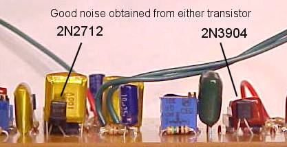
Good Noise Transistors 2N2712, 2N3904 and 2N5172
I made a board with multiple modules on it. You cansee the two different transistors I used for noise sources.
A 2N2712, 2N3904 or 2N5172 all make great noise.
Noise Source Parts List (Kindly provided by Daniel Vera of Finland)
| QTY. | Description | Value | Designators |
| 4 | Resistor 1/4 Watt 1% | 1M | R1,R2,R8,R24 |
| 8 | Resistor 1/4 Watt 1% | 100K | R3,R5,R10,R11,R12,R16,R23,R26 |
| 5 | Resistor 1/4 Watt 1% | 1K | R4,R13,R14,R18,R21 |
| 1 | Resistor 1/4 Watt 1% | 4.7M | R7 |
| 1 | Resistor 1/4 Watt 1% | 30K | R9 |
| 1 | Resistor 1/4 Watt 1% | 82K | R15 |
| 2 | Resistor 1/4 Watt 1% | 10K | R17,R22 |
| 1 | Resistor 1/4 Watt 1% | 47K | R19 |
| 1 | Resistor 1/4 Watt 1% | 3K | R25 |
| 1 | Potentiometer (1/2Watt) | 100K | R20 |
| 1 | Trimmer /Potentiometer (1/2 Watt) | 10K | R6 |
| 4 | Ceramic Capacitor(s) | 0.22uF | C1,C4,C5,C9 |
| 2 | Ceramic Capacitor(s) | 0.001uF | C2,C8 |
| 1 | Ceramic Capacitor | 0.002uF | C3 |
| 2 | Electrolytic Capacitor(s) | 10uF/16V | C6,C7 |
| 2 | Transistor NPN(s) | 2N3904 | Q1 & Q2 |
| 2 | JFET-input op-Amp(s) | TL084 | IC1 &IC2 |
| 1 | CMOS dual D-type flip-flop | CD4013 | IC3 |
| 4 | Silicon Switching Diode(s) | 1N914 | CR 2-5 |
| 1 | Light Emitting Diode (LED) | LED1 | |
| 6 | Phone Jack | 1/4" Jack | J1-J6 |