Ray Wilson authored this content while he was actively running MFOS as the founder and resident genius.
We retain the content because it reflects a valuable point of view representing that time and place.
Article by Ray Wilson
This is an intermediate to advanced project and I do not recommend it as a first project if you are just getting started in synths or electronics. Only the circuit and some explanation are shown here. A lot of project building, troubleshooting and electronics experience is assumed. Additionally, electronic equipment ownership (scope, meters, etc.) is taken for granted. If you are interested in building this project please read the entire page before ordering PC boards to ensure that the information provided is thorough enough for you to complete the project successfully.
Introduction
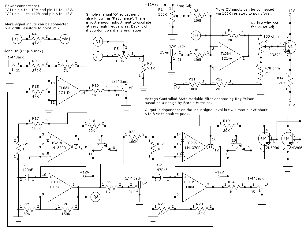
This will add a ton of timbres to your bag of tricks. This filter is also known as a Universal Active Filter. You get simultaneous High Pass, Band Pass, and Low Pass filtering. You can, of course, cascade two of these to obtain higher order filtering. The control voltage portion is just about straight from a Bernie Hutchins design. I love this filter. I built two into a module and am really pleased with the results. Now my synth has two of my low pass filters and two of these... I'm in filter heaven.Circuit Description
OK, I went back in and got it to work with 8 to 10 volt peak to peak signal amplitudes and made it output 8 to 10 volts peak to peak (note that this is when the Resonance is turned up and the Q ringing adds a couple of volts). If you overdrive the input you get some really funky sounding timbres so give it a try. I'm going to try and build this circuit using the buffers in the LM13700 to replace IC1B and IC1C. If it sounds as good as the current design it will mean that I can build this with one LM13700 and one TL082 (slightly cheaper than the TL084) so we can all save a buck or two.
Voltage Controlled State Variable Filter Schematic
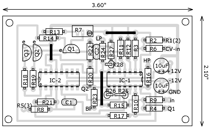
Voltage Controlled State Variable Filter PCB Layout (Component Side View)
This board is printed at the proper size when the distance between adjacentIC pads is exactly 1/10" and the distance across an IC pad layout is exactly 3/10".

Voltage Controlled State Variable Filter Parts Placement
NOTE!! that R25, R26, and R28 are vertically mounted. I kludged them in after I went back and worked the gain up a bit. The two 10uF caps are not on the schematic and are present for power supply bypassing. NOTE THAT THE TWO CHIPS FACE OPPOSITE DIRECTIONS!! When I was experimenting with this circuit I put the power to a TL084 backwards and the chip got so hot that it melted my breadboard, destroying the chip in the process (no kidding).
VC State Variable Filter Project Parts List
You can use 5% resistors if you don't have 1% they will work fine.
| Qty. | Description | Value | Designators |
|---|---|---|---|
| 5 | 1/4 Watt 1% Resistor(s) | 100K | R6, R2, R11, R17, R20 |
| 1 | 1/4 Watt 1% Resistor | 120K | R14 |
| 2 | 1/4 Watt 1% Resistor(s) | 150K | R26, R28 |
| 5 | 1/4 Watt 1% Resistor(s) | 1K | R16, R24, R22, R21, R23 |
| 2 | 1/4 Watt 1% Resistor(s) | 20K | R19, R18 |
| 1 | 1/4 Watt 1% Resistor | 270K | R9 |
| 2 | 1/4 Watt 1% Resistor(s) | 2K | R3, R12 |
| 2 | 1/4 Watt 1% Resistor(s) | 39K | R25, R27 |
| 1 | 1/4 Watt 1% Resistor | 470 ohm | R13 |
| 3 | 1/4 Watt 1% Resistor(s) | 47K | R10, R15, R4 |
| 1 | 1/4 Watt 1% Resistor | 9.1K | R8 |
| 2 | Ceramic Capacitor(s) | 470pF | C1, C2 |
| 1 | LM13700 OP-Amp | LM13700 | IC2-B, IC2-A |
| 1 | Operational Amplifier | TL084 | IC1-D, IC1-C, IC1-A, IC1-B |
| 5 | Phone Jack(s) | 1/4" Jack | J4, J5, J3, J1, J2 |
| 1 | Potentiometer | 100 ohm | R7 |
| 2 | Potentiometer(s) | 100K | R1, R5 |
| 1 | Transistor NPN | 2N3904 | Q1 |
| 2 | Transistor PNP(s) | 2N3906 | Q3, Q2 |