Ray Wilson authored this content while he was actively running MFOS as the founder and resident genius.
We retain the content because it reflects a valuable point of view representing that time and place.
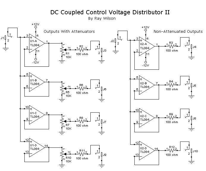
Article by Ray Wilson
This is an intermediate to advanced project and I do not recommend it as a first project if you are just getting started in synths or electronics. Only the circuit and some explanation are shown here. A lot of project building, troubleshooting and electronics experience is assumed. Additionally, electronic equipment ownership (scope, meters, etc.) is taken for granted. If you are interested in building this project please read the entire page before ordering PC boards to ensure that the information provided is thorough enough for you to complete the project successfully.
Introduction
This circuit allows you to use one control voltage to drive several modules. As you can see you can use either or both of these circuits or mix and match in the same module. In other words make two with non-attenuated outputs and two with attenuators or make them all attenuated or non-attenuated its up to you. The circuits are DC coupled which means they will faithfully pass your DC control voltages (not a cap in sight).Control Voltage Distributor II Schematic