Sound Lab Mini-Synth Guitar Trigger
Article by Ray Wilson
This is an intermediate to advanced project and I do not recommend it as a first project if you are just getting started in synths or electronics. Only the
circuit and some explanation are shown here. A lot of project building, troubleshooting and electronics experience is assumed. Additionally, electronic equipment ownership (scope, meters, etc.) is
taken for granted. If you are interested in building this project please read the entire page before ordering PC boards to ensure that the information provided is thorough enough for you to complete
the project successfully.
Introduction
Turn your Sound Lab into a guitar effects box with this simple circuit. The output of this circuit can feed into the Sound Labs VCF and VCA and can gate the AR generator.Some Samples of Cakewalk drums with some guitar played through the Sound Lab.
Funky Little Tune Mellow Tiny Tune Electronic Diminutive TuneCircuit Description
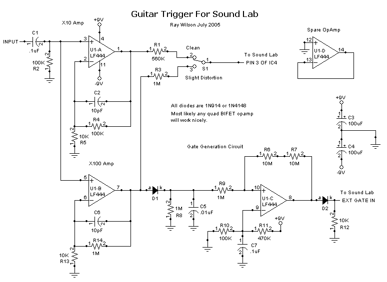
U1-A and associated components comprise a x10 amplifier that boosts your guitar signal for insertion to the Sound Lab's VCF and VCA. C1 capacitively couples the signal from your guitar into the amplifiers. R4 and R5 set the gain of the guitar pre-amp. You can adjust the gain by changing the value of R5 (higher value = lower gain, lower value = higher gain). C2 is to prevent unwanted oscillation in the op-amp's output. U1-B and associated components provides a gain of 100 for the signal. R14 and R13 set U1-B's gain in the same way that R4 and R5 set U1-A's gain. U1-B's output feeds a diode which charges C5 during positive signal excursions. R8 discharges C5 when the guitar signal stops sustaining. U1-C is wired as a comparator with hysteresis (positive feedback). The hysteresis is necessary so that you don't get gate chattering when the voltage on C5 is near the threshold set by R10 and R11. When the voltage on C5 goes above the threshold set by R10 and R11 (plus a bit more due to hysteresis) U1-C goes from low to high. This happens when you play the guitar (or other instrument connected to the input). D2 keeps the gate output from going negative. The gate out goes from ground to +9 volts and can be fed into the Sound Lab's external gate input. C3 and C4 try to keep the comparator's switching out of the audio. Feeding U1-B's signal to the Sound Lab (via R3) will overdrive it slightly giving a slight distortion effect. You can change the value of R1 or R3 if your guitar puts out a hotter or not as hot signal as mine. Increasing their values reduces the signal to the Sound Lab whereas reducing their values increase the signal fed to the Sound Lab. You can change R13 to make the gate more or less sensitive. Lower value more sensitive, higher value less sensitive. U1-B's gain is (R14 divided by R13) + 1. As the schematic says the audio output of this circuit goes to the Sound Lab's pin 3 of IC4.
Its extremely cool and fun to play with.
Sound Lab Mini-Synth Guitar Trigger [Schematic PDF]

Sound Lab Mini-Synth Guitar Trigger Parts List
| Qty. | Description | Value | Designators |
|---|---|---|---|
| 2 | 1N914 Sw. Diode(s) | 1N914 | D1, D2 |
| 1 | Ceramic Capacitor (S) | .01uF | C5 |
| 2 | Ceramic Capacitor (S)(s) | .1uF | C1, C7 |
| 2 | Ceramic Capacitor (S)(s) | 10pF | C2, C6 |
| 2 | Electrolytic Capacitor (S)(s) | 100uF | C3, C4 |
| 1 | LF444 Quad Op Amp | LF444 | U1 |
| 3 | Resistor 1/4 Watt 5%(s) | 100K | R2, R4, R10 |
| 3 | Resistor 1/4 Watt 5%(s) | 10K | R13, R5, R12 |
| 2 | Resistor 1/4 Watt 5%(s) | 10M | R6, R7 |
| 4 | Resistor 1/4 Watt 5%(s) | 1M | R8, R14, R3, R9 |
| 1 | Resistor 1/4 Watt 5% | 470K | R11 |
| 1 | Resistor 1/4 Watt 5% | 560K | R1 |
| 1 | SPDT Switch | SPDT | S1 |