Wire the front panel as shown for the production version.
Schematics are the same as for the production version.
You can use the value view of the production version but note that there are differences around the areas where the kludges are since that is where new pads were added to the PC board necessitating moving some components. Consult the schematic and parts list to find the values needed where differences in component placement exist.
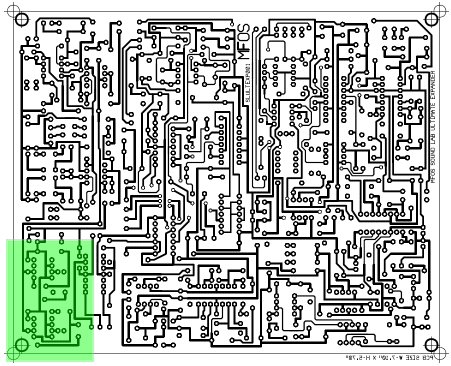
ULTIMATE EXPANDER Prototype PC Board Drawings
ULTIMATE EXPANDER EXPANDER Prototype Kludges
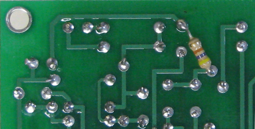
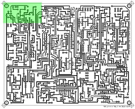
Adding R163 (47K resistor from junction of R123 wiper and C52 lead)This resistor stabilizes the ext signal amplifier. See next image for the relative area of the board for this kludge.
ULTIMATE EXPANDER EXPANDER Prototype Kludges
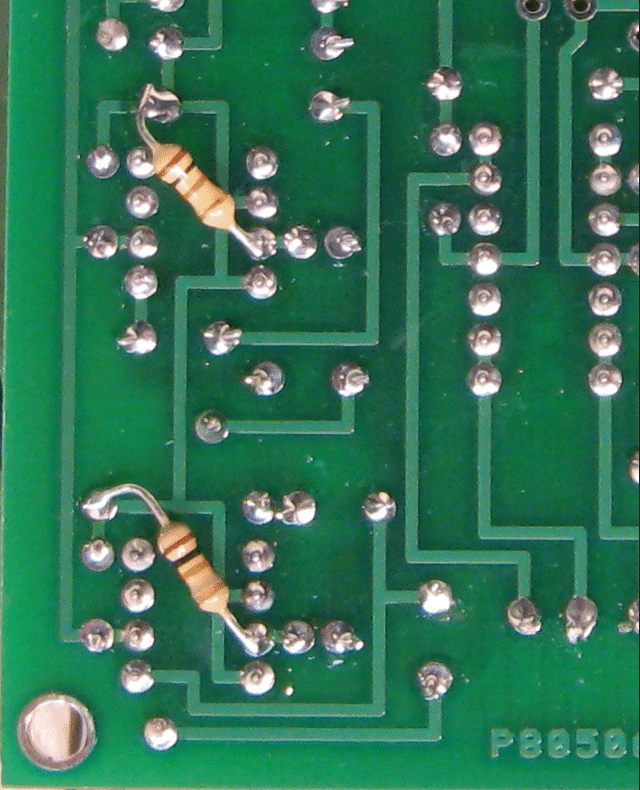
Adding R164 and R165 (10K resistors on pin 3 inputs of the LM386-4 amps U18 and U19.)These resistors stabilize the headphone amplifier inputs. See next image for the relative area of the board for this kludge.
ULTIMATE EXPANDER EXPANDER Prototype Kludges
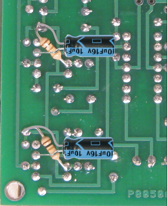
Adding C75 and C76 (10uF electrolytic caps on pin 7 bypass pins of the LM386-4 amps U18 and U19.)These capacitors improve power supply rejection in the headphone amplifiers. This obviously photo-shopped image is because I forgot to take a photo of this kludge before putting the unit back together for the nth time and was not taking it apart again. The 16V caps shown will be OK but I would go 35V. See next image for the relative area of the board for this kludge.
