Ray Wilson authored this content while he was actively running MFOS as the founder and resident genius.
We retain the content because it reflects a valuable point of view representing that time and place.
Article by Ray Wilson
Introduction
I'm going to show you the math-free intuitive method I used to design the filters for the MFOS Vocoder. Thanks to Texas Instruments and OKAWA Electronics designing filters is as easy as entering a few values and clicking 'Calculate'. Can you set up your own filter set customized to your preferences? Absolutely. The first thing you need to do is download the application from Texas Instruments known as: FilterPro™: Active Filter Design Application from here:You have to sign up for a free TI website account to get it. It is very simple and straightforward to do so. TI is a great resource for information and technology so it's a good idea to stay in touch with them. The full documentation for the FilterPro™ application is right there on the same page as a PDF download link. OK, you've downloaded and installed the app and the documentation.

Select Filter Type
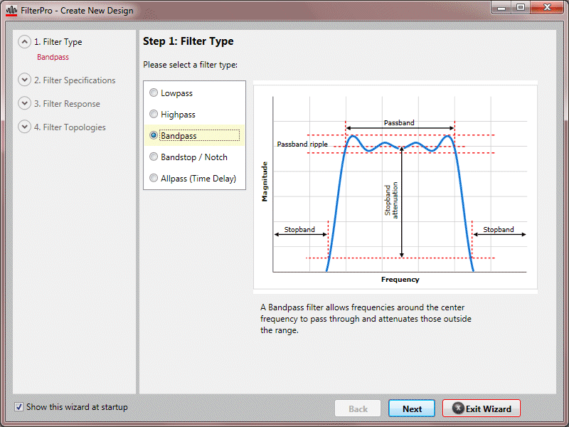
Start it up and "Filter Wizard" should pop up. If it doesn't then select Filter Wizard from the icon menu (top left page - icon with red sparkles). The first choice you make is filter type. We are choosing Bandpass. Of course if you need to design a new filter for the starting Lowpass or ending Highpass you would choose the appropriate filter type. Since most of the filters are band pass we are demonstrating it alone in the following.

Enter Filter Specifications
| Gain | I recommend gains in the 3 to 5 range. |
| Center Frequency | The frequency of interest for this band. For our example we set 1000 Hz. |
| Allowable Passband Ripple | I accepted the defult - 1 dB |
| Passband Bandwidth | This is the parameter that sets the Q of the filter or how selective it is. If you heard your voice through a high Q 2K filter you would sound like you were taking through an old phone. The Q pretty much works out to be center frequency divided by Passband Bandwidth. So for 1000 Hz and 200 Hz. bandwidth your Q will be very near 5 (moderate). Had we chosen 100 Hz for the Bandwidth the Q would be close to 10 (very high). With passband width set for 200 Hz. the signal through the filter will be attenuated down by 3 dB (about 70% of original amplitude) at 900 Hz on the low end and 1100 Hz on the high end. The higher the Q the sharper the filter will fall off after that in the high and low directions. |
| Stopband Bandwidth | Left at default. Experiment with this if you want to. |
| Stopband Attenuation | Left at default. Experiment with this if you want to. |
| Optional Filter Order | Check "Set Fixed" and select "2" from the dropdown. |

Accept Default Response Type Selection
Click next and accept the Response Type page's defult selection.

Select Multiple-Feedback (Single ended)
Click next and select Multiple-Feedback (Single ended).

Click "Finish" to Display the Calculated Values
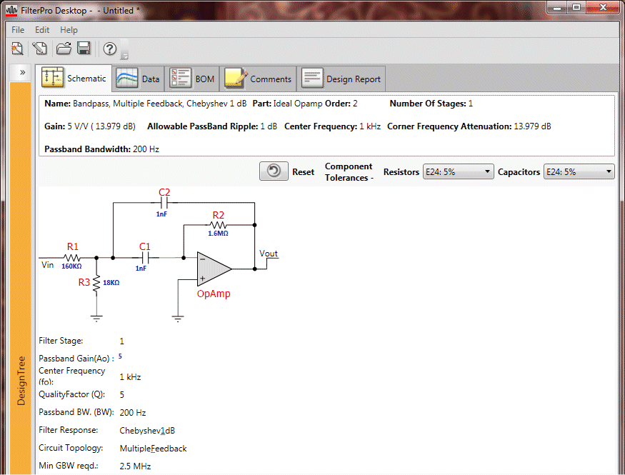
Very Important! Set the capacitor and resistor component tolerances to E24: 5% so that the component values displayed will be ones you can actually find. If you want to you can set the resistors to E96: 1% since they are far more available than low tolerance capacitors in values you need and prices you can afford. Stick to 5% (or better) for the caps. Lower cap tolerance will disappoint you when they are so far away from the value you expected (due to tolerance variations) that the filter's response will also not be what you expect. When you change the selection the schematic will redraw using the selected tolerances.

Increase the Input Impedance by Entering Lower Values for Caps
The next thing I do is lower the cap values (when you click a component's value text it becomes editable). When you hit enter after editing a value the app will recalulate the resistors for the new cap values. Lowering the cap value will not change the filter characteristics (gain, Q, etc) but it will increase the filter's input impedance. You can see here that changing the cap value to 1nF (.001uF) changed the input impedance from 16K to 160K. Remember that in the vocoder one op amp's output is driving the inputs to twelve filters so it is a good idea to keep the input impedance of the filters high. We're almost there.
Lowering the cap values by a factor of 10 raises the input impedance by a corresponding factor of 10. Note that the app recommends a minimum GBW (gain bandwidth product) of 2.5 MHz for the op amp used in the filter. The gain bandwidth at unity gain for the TL072CN is 3MHz so we are good to go. The GBW figure indicates at which frequency the op amp's output amplitude will be down by 3dB (approx 70% of original value) when used with unity gain. An ideal op amp would not have an upper frequency limit but in the real world they definitely do.

Fire up the OKAWA Electronics Online Filter Tool
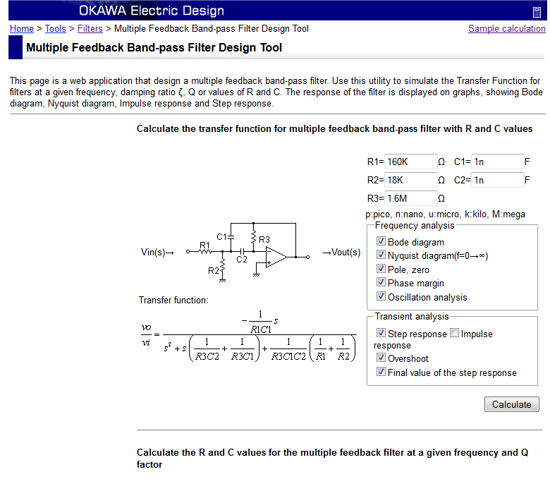
This tool is found here: Go to OKAWA Electronics Filter tools. Scroll down a bit and select the Multiple feedback Band-pass Filter Tools. Enter the values you found using the FilterPro™ tool and click the Calculate button.

Calculate Button Clicked - Calculation Completed
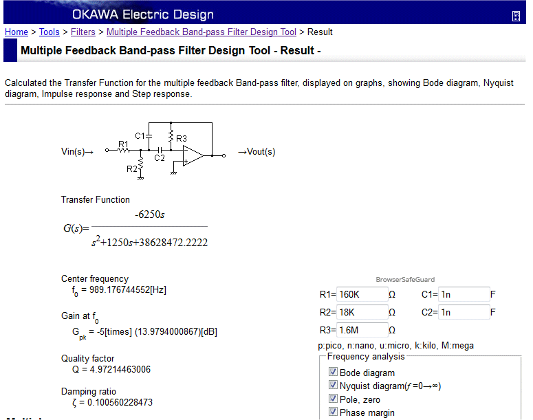
The calculation may reveal that the center frequency has moved a bit due to the tolerances used in the FilterPro™ calculation. Here we see that the center frequency is reported as 989 Hz. (11 Hz from ideal). You can choose to live with this or you can start to modify the values in the OKAWA calculator and see if you can get closer to the ideal. Notice that the gain and the Q came out very close to what we entered in the FilterPro™ tool. If you decide to modify the values using the OKAWA tool recognize that the Q, gain, and center frequency can shift significantly. Experiment with the tool to see how value changes of the various components change the the gain, Q, etc.

Record the Values
Make a work sheet to keep track of the values for each filter you design in this manner. You can breadboard the filter first or jump right to populating the PC board. In any case I hope this information helps you if you decide to modify your vocoder. If you were really crazy for vocoders you could actually parallel two MFOS vocoder boards and end up with a 22 or 24 channel volcoder. One board becomes the master and is fully populated while the other functions only as the extra bands. The second board does not need any of the non-filter band components (located to one side of the PC board). Connect points 1 through 6 between the two boards and voila the main board drives the second board and the second board contributes to the overall response of the main board's output.