Ray Wilson authored this content while he was actively running MFOS as the founder and resident genius.
We retain the content because it reflects a valuable point of view representing that time and place.
Article by Ray Wilson
WSG Original Recipe (with this PCB)
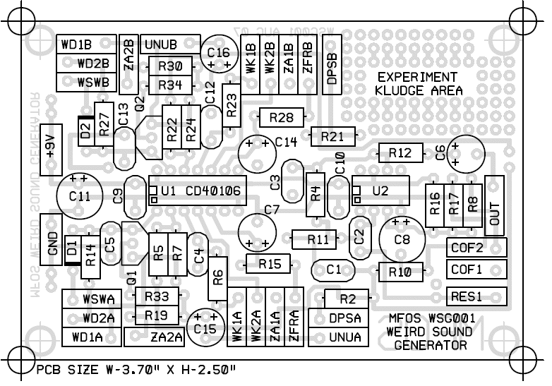
MFOS Weird Sound Generator PCB Parts Layout (Parts Side Shown) PDF
See the "Case Wiring" page for details.
- Resistors
- IC Sockets (or ICs if you are not using sockets... no sockets is a bad idea)
- Capacitors (Some caps are bigger and may overlap the IC sockets. Do not attempt to fully seat these larger caps (C7, C8 and C14) but instead leave a bit of lead slack so that they can bend away from the socket slightly. This will enable you to easily insert the ICs.)
- Everything else.
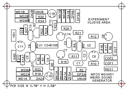
The Kludge Experiment area is for your contribution to Weirdsoundology. It is the fertile soil of discovery. It is the last true place of innovation on earth. It is... some extra area that I could not bear to let go naked. Hey benders... let's see whacha got!
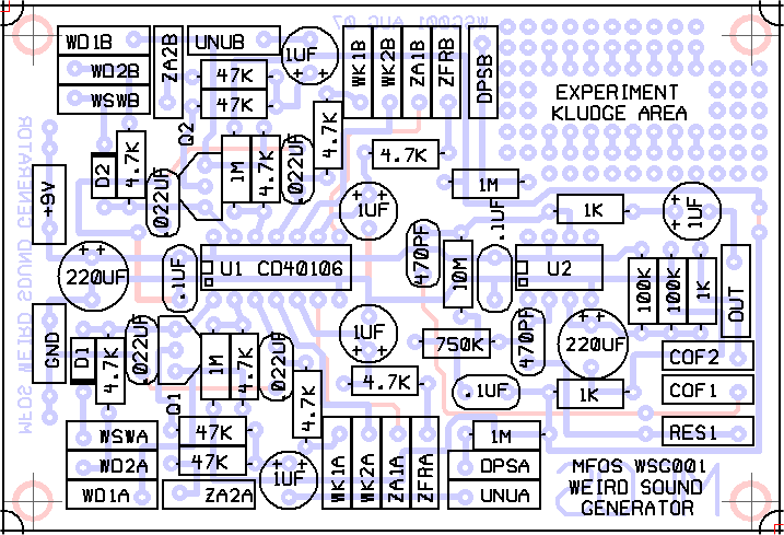
MFOS Weird Sound Generator PCB Parts Layout (Values Shown)
See the "Case Wiring" page for details.
- Resistors
- IC Sockets (or ICs if you are not using sockets... no sockets is a bad idea)
- Capacitors (Some caps are bigger and may overlap the IC sockets. Do not attempt to fully seat these larger caps (C7, C8 and C14) but instead leave a bit of lead slack so that they can bend away from the socket slightly. This will enable you to easily insert the ICs.)
- Everything else.
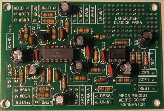
MFOS Weird Sound Generator Populated PCB
The electronic components that come with your kit may not look exactly the same as the parts shown in this picture. That's OK! All the parts that come with your kit will have the correct values and that is what matters. When you lay out your parts to check that they are all there you want to be concerned with the values not the physical appearance. The resistors will look very similar but the capacitors may vary in appearance. The 1/4 watt 5% resistor R35 (470K) is located on the front panel and not on the printed circuit board. See the "Case Wiring" page for details.
MFOS Weird Sound Generator PCB Bottom Copper (Parts Side Shown)
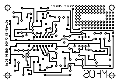
MFOS Weird Sound Generator PCB Top Copper (Parts Side Shown)
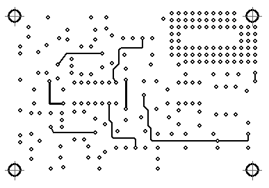
MFOS Weird Sound Generator PCB Top Silk Screen (Parts Side Shown)
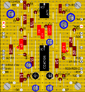
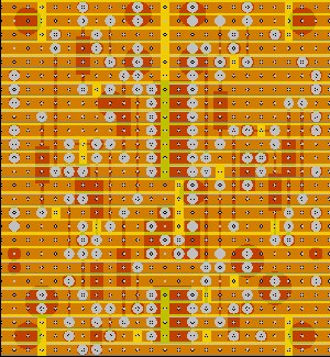
Andrew Sharp of Australia Shares His Strip-Board Layout (Click for Full Size Image)
Andrew did not include C9 and C10 battery power supply high frequency noise bypass caps. They are not necessary but are typically included in designs to provide high frequency noise bypass. If you want to include them just wire them across the plus and minus power pins of each IC.
| Component Side View (top) | Copper Side View (bottom) |
 |
 |
