|
||||||||||||||||||||||||||||||||||||||||||||||||||||||||||||||||||||||||||||||||||||||||||||||||||
| The MFOS SCOOP | In This Issue | MFOS Has Parts For Sale | ||||||||||||||||||||||||||||||||||||||||||||||||||||||||||||||||||||||||||||||||||||||||||||||||
|
Hi Everyone!
The MFOS SCOOP is being sent at your request to keep you in the loop regarding MFOS. MFOS' mission is to be the most informative synth-DIY site on the planet. We're here to help you keep imagining, keep inventing, and stay ingenious! When you click the Facebook "Like" button on the MFOS site it's as good as a contribution to our site. Thank you very much! If you have any suggestions about what you would like to see in an issue of The MFOS SCOOP email me.
|
This issue of The MFOS SCOOP has some great information.
New! Through the miracle of science we have Pocket Protectors free with orders over $50.00. Also available for sale separately. 
|
At
MFOS
finding parts is easy.
Enter parts in the search box and hit enter...
Check these cool parts out!
AD633AN Analog Multiplier
|
||||||||||||||||||||||||||||||||||||||||||||||||||||||||||||||||||||||||||||||||||||||||||||||||
|
||||||||||||||||||||||||||||||||||||||||||||||||||||||||||||||||||||||||||||||||||||||||||||||||||
|
||||||||||||||||||||||||||||||||||||||||||||||||||||||||||||||||||||||||||||||||||||||||||||||||||
|
||||||||||||||||||||||||||||||||||||||||||||||||||||||||||||||||||||||||||||||||||||||||||||||||||

|
||||||||||||||||||||||||||||||||||||||||||||||||||||||||||||||||||||||||||||||||||||||||||||||||||
|
||||||||||||||||||||||||||||||||||||||||||||||||||||||||||||||||||||||||||||||||||||||||||||||||||
|
||||||||||||||||||||||||||||||||||||||||||||||||||||||||||||||||||||||||||||||||||||||||||||||||||
|
This Tech Bench goes over a simple AD envelope generator design that only uses two op amps. You can make one with a
dual op amp package or design a board for two using a quad op amp package. The op amps need to be
the JFET input type and the versatile TL072 (or TL074) fills the bill perfectly. This is the same
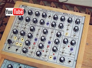
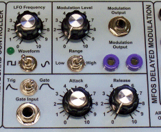
ADEG design as that used in the MFOS Sound Lab Mini-Synth Mark II and the MFOS Delayed Modulation Module.
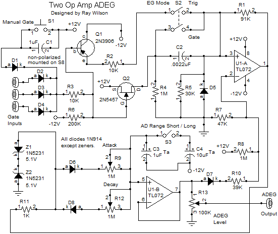
Lets walk through the circuit and learn a bit about how it works. The expected gate input should go from ground (or below) to about +4V (or more but no higher than the supply voltage). In it's quiescent state U1-A's output sits at it's negative saturation voltage of about -10.5V. That voltage is applied to the two kathode to kathode 5.1V zener diodes to ground via 1K current limiting resistor R11. When the output of U1-A is low (negative saturation voltage) Z2 is forward biased but Z1 is reverse biased and zeners at about -5.1V. When the output of U1-A is high (positive saturation voltage) Z1 is forward biased but Z2 is reverse biased and zeners at about +5.1V. Thus the output of the ADEG is constrained to be between about -5.1V (quiescent state) and +5.1V (ADEG output maximum). When the AD Range Short/Long switch (S3 SPST toggle switch) is closed C4 is put in parallel with C3 which effectively changes the AD timing cap from 1uF to 11uF and subsequently makes the Attack and Decay times about 10 times longer than when the AD Range switch is open. We will only mention C3 going forward for simplicity. When the output of U1-A is low D8 is forward biased until C3 discharges to about -5V. U1-B is used as a high impedance voltage follower and simply buffers the voltage on C3. Use of low leakage tantalum caps is recommended for C3 (1uF 25V Ta cap) and C4 (10uF 25V Ta cap). R9 and R12 are 1M audio taper pots. When the output of U1-A is high C3 charges via R11 and D6 toward +5.1V at the rate set by 1M audio taper Attack control R9 and when the output of U1-A is low C3 discharges via R11 and D8 toward -5.1V at the rate set by 1M audio taper Decay control R12. The charging and discharging of C3 buffered by U1-B is the actual envelope output by the ADEG. Diodes D6 and D8 prevent the Attack and Decay controls from interacting. Capacitor C3 (1uF tantalum capacitor) is discharged to -5V under normal conditions. Thus normally the output of U1-B is about -5V. This reverse biases D7 so no current flows through it when U1-B's output is low (-5V). With U1-B's output at about -5V the network of resistors connected to the inverting input of U1-A (R7 - 47K to ground and R8 - 1M to +12V) biases the inverting input of U1-A so that it's voltage is above that on U1-A's non-inverting input. This is what keeps U1-A's output at negative saturation under normal conditions (ADEG not gated or triggered) First we'll consider triggered mode operation. S2 (DPST toggle switch) is open in triggered mode. When a gate is applied to one of the gate inputs or the Manual Gate pushbutton is pressed current flows through the forward biased gate input diode, through R3 (10K resistor) and drops voltage across R6 (200K resistor to -12V). If the gate voltage is about 5V the voltage dropped on R6 is about 3.5V (don't forget the diode drop). This voltage across R6 simultaneously turns on Q2 (2N5457 N channel JFET) and turns off Q1 (2N3906 PNP transistor). When Q2 turns on current flows from Q2's source to Q2's drain and drops +12V across R4 (1M resistor). The leading edge of the step of voltage applied to R4 is propogated through C2 (.0022 uF ceramic cap) and a narrow positive pulse is dropped on R5 (30K resistor). When the gate goes low D5 keeps the non-inverting input from seeing a negative spike and C2 discharges through R4 to ground. This narrow positive pulse applied to the non-inverting input of U1-A brings it above the voltage on it's inverting input and thus U1-A's output goes high (positive saturation voltage). R1 (91K resistor) provides positive feedback that now holds the output of U1-A high until current through R11 flows through D6 and begins to charge the AD timing cap(s) at the rate set by the Attack control until the output of U1-B rises high enough to forward bias D7 (1N914 diode) and push current through R10 until the voltage on U1-A's inverting input is once again higher than that on it's non-inverting input and the output of U1-A goes low (negative saturation voltage). When U1-A goes low current flows the other way via R11 and D8 and discharges the AD timing cap(s) at the rate set by the Decay control to -5V. To reiterate the two zeners keep the output voltage within about -5V to +5V because the junction of Z1's anode, D6's anode and D8's anode is constrained to stay within that range by the back to back zeners. U1-B is basically a high impedance voltage follower for the voltage on C3 (or C3/C4 combination). In gated mode (S2 closed) the operation of the ADEG changes in this way. The drain of Q2 is now connected to the non-inverting input of U1-A so that instead of seeing a pulse U1-A's input sees a constant +12V which overrides the bias levels of the non-inverting input and keeps the output of U1-A and thus the ADEG high until the gate is released. Upon gate removal Q1 comes into play because it is turned on and thus causes the non-inverting input of U1-A to see -12V bringing it below the voltage on it's inverting input thus causing U1-A to go low (negative saturation voltage) and subsequently the ADEG enters the decay phase immediately. In triggered mode a trigger always results in the ADEG output going to it's maximum level and then entering the decay phase but in gated mode the output of the AD rises when the gate is present, stays high as long as it is present and then enters the decay phase on gate removal. Even if the output of the ADEG has not attained it's maximum output level it will still enter the decay phase upon gate removal in gated mode. The output (ADEG output) sees the envelope voltage whose level is set by ADEG Level pot R13 (100K linear taper). There you have it. The versatile dual op amp is the only IC you need in this design. With such a simple design there is no reason not to have all the ADEGs you want in your modular. Good building!
AD Envelope Generator With A Dual Op Amp Project Parts List
|
||||||||||||||||||||||||||||||||||||||||||||||||||||||||||||||||||||||||||||||||||||||||||||||||||
|
||||||||||||||||||||||||||||||||||||||||||||||||||||||||||||||||||||||||||||||||||||||||||||||||||
| If you're not a web developer this story will be really boring... Even if you are it might be but... About two years ago I had grandiose visions of a Java powered MFOS that would bring the coolest tools ever to the synth-diy community. I went out on a limb and used what appeared to be one of the powerful platforms that looked like it would be around for a while: Java Struts-II with Tiles II and even a bit of Spring thrown in for good measure. In two words... bad decision. The reason is that you really need to have a provider that is dedicated to supporting and maintaining the Java platform and less and less hosts are. Lunar Pages which is where I was hosting was outstandingly BAD at hosting Java and I (and worse my customers) would meet with the web server's equivalent of the blue screen of death far more often than I dreamed possible. Service tickets would be met by the usual "everything seems to be working fine now" response and I knew I would have to take some action that would provide a better experience for my visitors and customers and soon. Enter Godaddy hosting and PHP. PHP (which I have known for several years) is quickly becoming the most popular platform for web development in the hosted site world and Godaddy seems to be doing a good job. I re-wrote the MFOS site in PHP and I feel it responds better now and I have NEVER met with a server error page (fingers crossed). So bottom line. I hope you are finding the MFOS site to be more available and less prone to server problems. I continue to host the tools that used to be on the MFOS site over on the Lunar Pages hosted site: http://www.solderplanet.com. Sorry if you encounter errors there and eventually that site will be moved to Godaddy PHP hosting (after a fair piece of recoding). So my advice, host with Godaddy, use PHP in your dynamic sites and think long and hard before using Java technology for your hosted site. | ||||||||||||||||||||||||||||||||||||||||||||||||||||||||||||||||||||||||||||||||||||||||||||||||||
|
|
||||||||||||||||||||||||||||||||||||||||||||||||||||||||||||||||||||||||||||||||||||||||||||||||||


