Ray Wilson authored this content while he was actively running MFOS as the founder and resident genius.
We retain the content because it reflects a valuable point of view representing that time and place.
Article by Ray Wilson
Prototype PCB Support Documents
Ideas
I am going to present some ideas for using the Synth-DIY Experimenter Board here and I hope you think up some of your own. I'm certain you can make some very interesting sound generators using some or all of the modules on the board. I am going to present a full blown use of the board and how to use only half of it. In this way I hope you see that you can mix and match to make up your own customized sound generator using the Synth-DIY Experimenter Board.
First I explain the layout of the kludge area which contains the two spare op amps so you are familiar with the layout and which pads connect to what. I explain how to use all of the modules on the PC board in the Full Version in the first section, including using the kludge area to create a couple of audio mixers. If you want a simpler version I also present the "Half Sandwich" version, so named because there are just times when a half sandwich will do. This version uses the PCB but only one of each of the dual modules. This results in a lower cost sound effects box albeit with half the capabilities of the full version. In the YouTube videos that accompany this project I will demonstrate the effects you can expect with the full version and the half version. Both will probably surprise you. The parts list contains the BOM for the Full version, the "Half Sandwich" version and the kludged mixers section. It is important that you order the parts for the appropriate version and the kludge area if you make either of these projects.
As I come up with more ideas I will post them here or at the bottom of this page.
Flash! MFOS Micro Sample & Hold Works with the Synth DIY Experimenter Board... Read All About It!
Just got done testing my Synth-DIY Experimenter Board project with the MFOS Micro Sample and Hold and it worked perfectly. Here is the link to the stand alone version of the project which can use the Synth-DIY Experimenter Board modules for input voltages and control the CV controllable modules with it's output. It's a match made in heaven. Go to the MFOS Micro Sample and Hold Project
The Kludge/Idea/Proto Area Explained...
This is the Kludge/Idea/Proto Area of the PC board. The pink pads and lands are the top copper layer and the light blue pads and lands are the bottom copper layer. I have superimposed two op amp symbols and show the pins of the two spare TL074 IC op amps that are available for your use. You can do a lot of interesting things with two spare op amps. The blue lines show the pads that are connected if you insert the jumpers onto that section of the board (they are legends on the PC board). If you don't use this area I suggest that you insert the jumpers which connect the outputs of the op amps to their respective inverting inputs. Two jumpers also connect the non-inverting inputs to ground. This quiets the inputs of these op amps and keeps them from floating around or oscillating. If you don't read this and don't jumper them it is not the end of the world as we know it. The op amps will probably find a leakage path to something close by and assume that level.I have marked the traces that are +V, -V and Ground and again which are connected to the spare op amps' pins. All of the unconnected pads are for mounting components to support your use of the op amps. The op amp pins also have several connection points to use as well. Mounting resistors vertically is a good idea when you are crunched for space.
The Kludge/Idea/Proto Area
An Example Using The Kludge/Idea/Proto Area For Mixers
PLEASE NOTICE that I do not use the recommended jumpers since I added circuitry to the kludge area. They are only for when you don't use the kludge area for additional circuitry. Here I have used the kludge area to accommodate two audio mixers. One of the mixers is for mixing signals to send to the outside world (thus the 1/4" output jack in the schematic below) and the other is for mixing signals from the sound generator to feed the combined output into a filter or a vca (thus the banana output jacks in the schematic below). All of these components fit nicely into the kludge area. The output markings (MIX1, MIX2, MIX3, MIX4 and MIXOUT for the Main Mixer) and (A, B, C and D for the Signal Mixer) correspond to where the circuits connect to the proposed front and auxiliary panels I show below. The circuit is explained in the text above the Schematic Page 7 below.
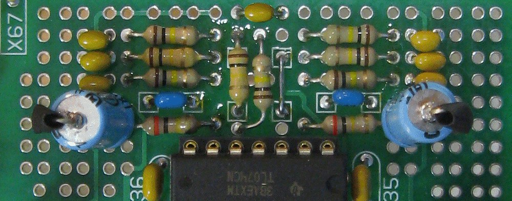
Kludge Area With Components Installed For Mixers
I took a photo of my kludge area before finishing up the wiring of this section. The components fit quite nicely as you can see. You can also see why I suggest you buy small 1uF aluminum non-polarized caps for the project. I had some larger 1uF non-polarized axial caps on hand which I used. I insulated the one lead from the case with shrink tubing due to the cramped quarters for the (IMHO) too large caps.
Corresponding Schematic For Using The Kludge/Idea/Proto Area For Mixers
We used the two spare op amps as inverting audio mixers. They are both very similar in design except for the fact that the Main Mixer permits one of the inputs to be applied to either the inverting or the non-inverting input of U9-B. This allows you to mix "out of phase" signals which can result in some cool effects. When the switch is set to send the input to the inverting input then the non-inverting input is grounded and vice versa. Both mixers have the potential for adding gain of up to 2 for lower level signals so be aware that setting the input levels too high for strong signals may result in distortion in the output. Both mixers have a 47pF stabilization cap in parallel with the feedback resistor since the op amps are only internally compensated for a gain of one.
Using All Of The Experimenter Board's Circuits For A Giant Sound Effects Box
Because I, of course, had to build and evaluate the PC Board and circuitry to make sure everything worked properly before unleashing this project on the world I figured I might as well just make a gigantic sound effects box. You can make this too or you can make the "half a sandwich idea" version shown later on the page which just uses 1/2 of the circuitry or 1 of each pair of modules and of course the noise generator.Again keep in mind that you can use whichever sections of the board you want. I show you how to "pacify" any section "halves" you don't use on the tab entitled "Full PC Board". If you don't plan to use an entire section of the board simply do not install any of the ICs or components for that section and you will be good to go.
Since all of the preceding project pages explain the operation of everything on the board I am going to go straight to the panel layout and wiring for the giant sound effect box version.
Building Suggestions
No matter which version you make or which modules you choose to use, these directions apply.
- Populate the PC Board but do not plug in the chips.
- Apply power to the PCB and make sure the correct voltage is present on the chip socket power pins.
- Remove power and plug the chips into the sockets.
- Install the components on the panel.
- Interwire the components on the panel.
- Attach wires long enough to comfortably connect to the PC board to the points that will go to the circuit board keeping each module's wires separate. Don't wire tie yet!
- Connect the wires to the PC board as indicated on the assembly drawing.
- Apply power and test each module.
Giant Sound Effects Box Panel Suggestions
When using a builder contributed panel suggestion unless it is accompanied by a wiring diagram I suggest that you prepare one for yourself to ease the panel wiring phase of the project and to avoid panel wiring mistakes.Builder Contributed Panel Ideas
Mark Pieper's Suggested Panel (Click image for scalable PDF)
MFOS Panel Layout Suggestion (Corresponds with the panel wiring diagram which follows).
This is a very utilitarian front panel layout meant to illustrate the interface and wiring. The PDF is 1:1 scale and can be used to make a front panel. If you want to make a front panel here is one way to do it that works for me: How To Make Front Panels
Larger Clearer Image Scalable PDF
Giant Sound Effects Box Panel Wiring
Here is the panel wiring diagram. When I created the schematics I had a +/-12V power supply in mind which is why you see it all over the place. However this circuit works perfectly with +/-9V which you can obtain using two nine volt batteries. Two Nine Volt Battery SupplyWhen you are populating the panel I suggest this order of component installation to ease assembly:
- Install the banana jacks.
- Install the switches.
- Install the potentiometers.
I like to populate the PC board, then populate the panel, then I wire up the panel. All of the +12V connections should be wired together and a wire should be available to attach to the PC board. All of the -12V connections should be wired together and a wire should be available to attach to the PC board. All of the Ground connections should be wired together and a wire should be available to attach to the PC board. As I stated you need to substitute your power supply if you use a different one. To clarify, if you use +/-9V then the +12V connections will turn into your +9V connections, the -12V connections will turn into your -9V connections and ground will always be ground.
Attenuators Each attenuator is simply a potentiometer and two banana jacks wired as a variable voltage divider. The banana jack labeled "In" goes to one side of the pot and the other side of the pot is grounded. The center connection of the pot is connected to the banana jack labeled "Out". This allows you to adjust the level of any of the outputs of the other modules by plugging it's output into the attenuator's "In" and then connecting the attenuator's "Out" to another module's control voltage input. Setting the attenuator knob all the way counter-clockwise reduces the signal at the "Out" jack to 0 and setting it all the way clockwise applies the full level of the signal at the "In" jack to the "Out" jack. Of course you can adjust to any level in between using the pot. For example, taking the output of one oscillator into the attenuator and applying the output of the attenuator to the other oscillator's CV input results in some strange modulation sounds as you vary the frequencies of the two oscillators and the amount of modulation from one to the other via the attenuator control.
Try to wire the panel in such a way that you don't have a bunch of wires soldered to one place. I try to wire my panel so that I have at most three wires going to any one connection. More than that is not a crime (What are you in for..? Murder. How about you? I attached too many wires to one place... sigh) and will work fine as long as you don't end up getting stuck trying to solder four or more wires to one lead of an LED since it's not very durable.
If you decide to make your own panel and use 1/4" phone jacks remember two things: 1) the connections called out in the drawing (X1, X2, etc.) get connected to the tip terminal and 2) that if your panel material is conductive and the jacks have metal chassis then if you connect one of the jack's ground connections you have grounded them all (which is good). If they are plastic or don't electrically connect the ring to the mounting then you need to connect all of the ring connections to ground.
Wires that carry high level signals like the outputs of oscillators or LFOs can reflect the signal passing through them into adjacent wires via capacitive and/or inductive coupling so when wiring your panel try to keep them away from the inputs to the VCAs, VCFs and the White Noise connection. You can use coax cable to connect the high level signals from the PCB to the panel to reduce the possibility of reflected signal. You only need to connect one end of the coax cable ground to circuit ground. You can use coax cable to connect the mixer pots to the PCB to reduce reflected signals from polluting the mixer. Again remember you only need to connect one end of the coax cable ground to circuit ground.
Larger Clearer Image Scalable PDF
Powering The Project
As I have tried to emphasize throughout this project's documentation, it can be powered from +/-9V or from +/-12V and where you see +12V or +V in the schematics or explanations you substitute your power supply's positive output. Where you see -12V or -V in the schematics or explanations you substitute your power supply's negative output. Ground is always ground regardless of the supply voltage.For newbies I always suggest a battery supply for safety, ease of construction, and availability. This supply applies to either of the projects (Full or "Half Sandwicch") and will run either unit for a decent amount of time. The illustration shows how to wire the power switch shown in the front panel wiring diagrams. I always use DPDT (Double Pole Double Throw) switches in my projects even when I only need DPST (Double Pole Single Throw) because I only have to buy one type of switch instead of two and the DPDT works perfectly as a DPST. Thus in the illustration you see two power switch terminals which are not used. All we are doing is switching the +/-9V potentials from the batteries so that they are either connected to the PCB (unit is on) or they are not (unit is off). Leaving the unit on will kill the batteries overnight so remember to turn it off unless your dad works for Duracell.
Building a wall wart supply is a project of it's own but if you intend to get into synth diy you are going to have to eventually start building line powered supplies. The MFOS Wall Wart supply project is a good choice for this unit. If using the wall wart supply the front panel switch becomes unnecessary since I recommend simply unplugging the wall wart when the unit is not in use. MFOS Wall Wart Supply Project
|
|
Sound Effects Box Auxiliary Panel Layout
As usual the last minute additions to my Sound Effects Box of the extra mixer and the gate outputs from the LFOs necessitated an auxiliary panel. So here it is in all it's simplistic glory. As you can see the full version differs from the "Half Sandwich" version in that since there is no LFO2 we don't need an output for the LFO2 Gate.
Sound Effects Box Auxiliary Panel Wiring
The wiring is pretty straight forward and the labels (A,B,C and D) correspond with the schematic for the mixers made on the kludge area drawing above. The points X68 and X69 come from the LFOs and are used to add repeat gate functionality to the AR generators. The "Half Sandwich" version does not have the LFO2 Gate output.
"Half Sandwich" Sound Effects Box Panel Layout
As previously stated, this version uses half of each of the dual modules on the PCB and results in a fun sound effects generator for a good deal less components and hence money.
"Half Sandwich" Sound Effects Box Panel Wiring
Most of the comments above in the "Giant Sound Effects Box Panel Wiring" above apply to building this version too. Please read them over before starting your panel component population and wiring.
Prototype PCB Support Documents