Ray Wilson authored this content while he was actively running MFOS as the founder and resident genius.
We retain the content because it reflects a valuable point of view representing that time and place.
Article by Ray Wilson
Voltage Controlled Amplifiers Schematic (Page 3) PDF
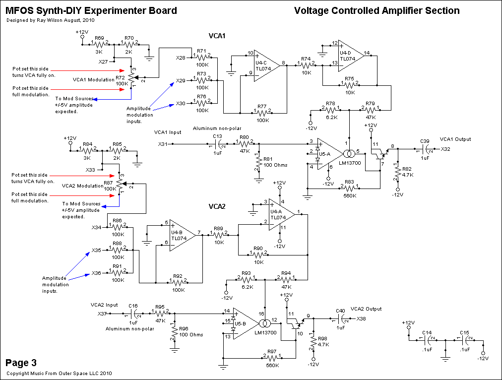
The "Voltage Controlled Amplifiers" are useful for controlling the amplitude of the signal fed through them via control voltage. They are simple VCAs and have a linear response to control voltage but function quite nicely and will give you another sound shaping component for your monster sound generator.I am going to describe the operation of VCA1 located at the top of Schematic Page 3 Voltage Controlled Amplifier Section. For more information regarding using the LM13700 for a ton of applications see National Semiconductor's National Operational Amplifiers Databook. VCA2 functions in exactly the same manner as VCA1 and thus it's operation will not be described.
The LM13700 Dual Transconductance Operational Amplifier is the heart of this circuit. The signal flowing through it is controlled by applying current to it's bias input pin 1. The input signal is applied to X31 (one end of C13 1uF non-polarized aluminum capacitor) and is attenuated by R80 47K and R81 100 Ohm resistors so that +/-3 volt level signals will not cause distortion. The attenuated signal is fed to the non-inverting input of U5-A (LM13700 Dual Transconductance Op Amp). Pin 4 of U5-A is connected to ground. The bias signal (level shifted control voltage) is applied to pin 1 via R79, 47K resistor. Resistor R78 is used to bring the bias input level closer to -V which is the condition in which the transconductance is at it's minimum (ideally 0). R83 560K resistor is used to bias the output so that it operates about ground. I attempted to get a gain of one at maximum control voltage although due to variation between LM13700 chips your mileage may vary. Resistor R82, 4.7K to -V is the output load resistor needed to bias the output pair into proper operation. The output of U5-A (pin 8) is connected to the outside world via C39 (1uF non-polarized aluminum capacitor) which connects to X32.
The control voltage mixer is comprised of U4-C and U4-D and associated components. U4-C is the actual control voltage mixer. It provides a gain of one for the control voltages which are connected to it via X28, X29 and X30. R71, R73, and R76 (all 100K) are the control voltage input mixer resistors and R77 100K feedback resistor sets the gain of the mixer to 1. Voltages in the range of +/-3V are expected. R72 100K panel mounted pot can turn the VCA all the way on by adjusting it toward the junction of R69, 3K resistor and R70, 2K resistor. Or it can allow the VCA to be modulated by the modulation source connected to the other end of the pot (which connects to a front panel modulation in jack).
U4-C inverts the control voltages connected to it's input so we use U4-D as an inverting buffer with a gain of 1 to re-invert them. Resistor R74, 10K is the input resistor to U4-D's inverting input and R75, 10K is the feedback resistor which sets the gain to 1. R79 47K resistor limits the current fed to the bias input pin of U5-A (pin 1) and R78 pulls the pin heavily toward -V. This is because current flows into the bias pin when the potential on it is above -V culminating in maximum VCA throughput when the voltage on U5-A pin 1 is at ground potential. When the potential at U5-A pin 1 is near -V the amplifier is essentially shut off. So the result of the CV mixer is that voltages on the inputs X28, X29 and X30 in the range of -3 to +3V are translated to the correct currents to control the VCA quite nicely.
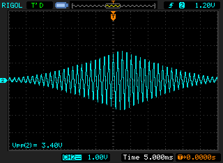
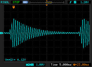
VCA Scope Photos
Oscillator 1's triangle wave is being fed into the vca as it is modulated by the LFO's triangle wave and the AREG.
| LFO Modulation | AR Modulation |
|
|
Voltage Controlled Amplifiers PCB Parts Layout (Parts Side Shown)
I find this one useful for trouble shooting since the designators on the PC board are covered by the installed components.
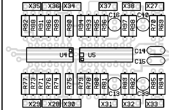
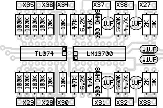
Voltage Controlled Amplifiers PCB Part Value View (Parts Side Shown)
I find this one useful for populating the PC board since I don't have to continually refer back to the schematic to know the value for a designator.
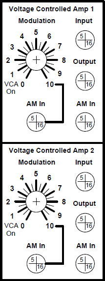
Voltage Controlled Amplifiers Front Panel Template
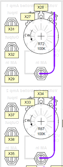
These front panel layouts are suggestions and are meant to illustrate the circuit's user interface and wiring between the panel and the PC board. I'm certain you can come up with a much cooler looking panel but this utilitarian version will certainly work to get you started.
Voltage Controlled Amplifiers Front Panel Wiring
Voltage Controlled Amplifiers Project Parts List
Resistor Color Chart For Resistors Used In This Circuit
The resistors should be carbon composition or carbon film.Use 1/4 watt resistors because 1/2 watt will be too big for the board.
| Qty. | Description | Value | Designators |
|---|---|---|---|
| 1 | LM13700 Dual gm OpAmp | LM13700 | U5 |
| 1 | TL074 Quad Op Amp | TL074 | U4 |
| 2 | Potentiometer Linear Taper | 100K | R72, R87 |
| 2 | Resistor 1/4 Watt 5% | 100 Ohms | R81, R96 |
| 8 | Resistor 1/4 Watt 5% | 100K | R71, R73, R76, R77, R86, R88, R91, R92 |
| 4 | Resistor 1/4 Watt 5% | 10K | R74, R75, R89, R90 |
| 2 | Resistor 1/4 Watt 5% | 2K | R70, R85 |
| 2 | Resistor 1/4 Watt 5% | 3K | R69, R84 |
| 2 | Resistor 1/4 Watt 5% | 4.7K | R82, R98 |
| 4 | Resistor 1/4 Watt 5% | 47K | R79, R80, R94, R95 |
| 2 | Resistor 1/4 Watt 5% | 560K | R83, R97 |
| 2 | Resistor 1/4 Watt 5% | 6.2K | R78, R93 |
| 4 | Capacitor Alum. Nonpolarized (small w/radial leads) | 1uF | C13, C16, C39, C40 |
| 2 | Capacitor Ceramic | .1uF | C14, C15 |
Miscellaneous
- 1/16" thick aluminum plate for mounting the pots and switches.
- Assorted hardware 1" 6-32 nuts and bolts, 1/2" #8 wood screws, etc
- Knobs for potentiometers, wire, solder and typical assorted electronics hand tools.
- Digital volt meter and a signal tracer or oscilloscope for testing.