Ray Wilson authored this content while he was actively running MFOS as the founder and resident genius.
We retain the content because it reflects a valuable point of view representing that time and place.
Article by Ray Wilson
Features
- Four separate Three input mono Audio mixers
- Each pair is switchable to become a Six input Audio mixer
- Each mixer includes a selectable high gain channel
- Single sided board layout for easy home production
Introduction
This Quad Audio mono mixer can be used to create sub-mixes in your modular or to amplify an instrument whose signal you want to experiment with. It is basically four three input audio mixers. Each pair of mixers can be switched to produce two six input mono mixers.
Schematics
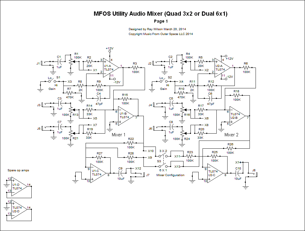
Schematic Page 1
View as PDFOp amp U3 and associated components comprise mono mixer 1. Op amp U3-A provides the switchable high-gain channel for mixer 1. The signal applied to J9 is fed via 1uF non-polarized aluminum cap C11 to one end of R29 (100K input level pot) used as a variable voltage divider (the other end is grounded). The adjusted signal on the wiper of R29 is fed to R30, 20K resistor which is connected to the non-inverting input of U3-A. U3-A's feedback resistor R37 is paired via switch S4 with either 2K (resistor R36) to ground (S4 is closed, gain is 50) or 472K (R35 470K series with R36 2K) (S4 is open gain is 1.21). Capacitor C14 suppresses unwanted op amp oscillation.
Op amp U3-B is used as an inverting mixer. Both of the adjustable signals coming from J11 and J13 and the output of U3-A are mixed via resistors R31 (100K), R42 (33K) and R48 (33K). The signals from J11 and J13 are capable of up to a gain of three. The optionally amplified U3-A signal sees a gain of one through U3-B. The inverted output of U3-B is fed to the switching network which facilitates changing each mixer pair's function to 6x1 instead 3x2. Switch S6 either sends the inverted outputs of U3-A and U4-B to their respective output inverter buffer or to both of them.
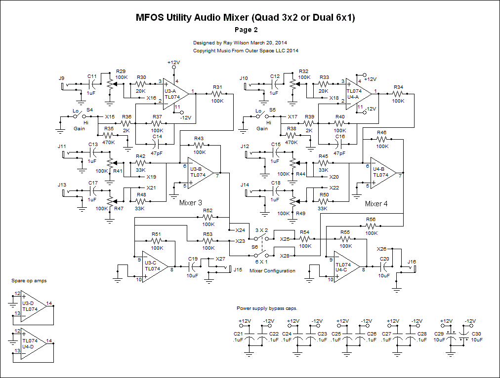
Op amp U4-B and associated componented work in exactly the same way to form the second mixer of this pair. The circuitry on page two functions in the same way as that on page one. Again the designators have been changed to protect the innocent. Lots of bypass caps throughout to keep the circuitry quiet.
Schematic Page 2
View as PDFSee Schematic Page 1 for Circuit Description
PC Board Information
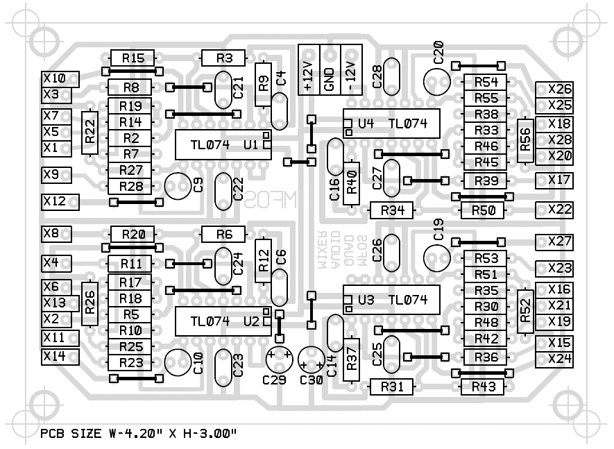
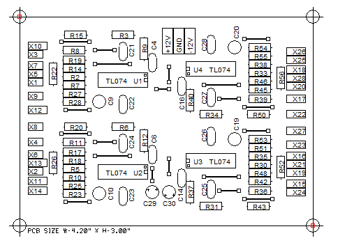
Parts Layout With Component Designators
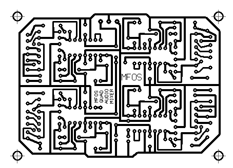
- This is a single sided board that you can make at home.
- This view shows the designators useful when trouble shooting.
- All jumper indicators must be shorted with number 22 AWG solid wire or equivalent.
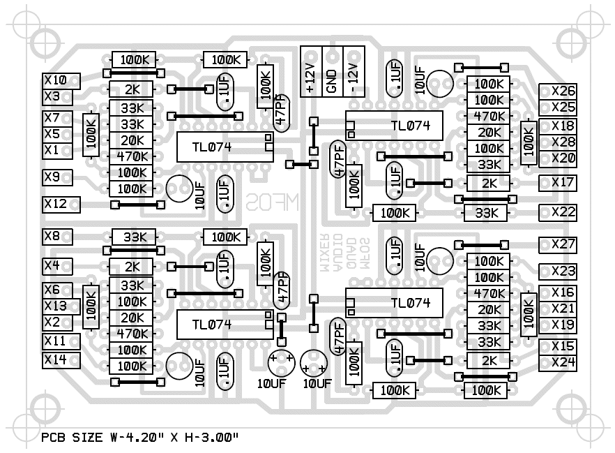
Parts Layout With Component Values
- This is a single sided board that you can make at home.
- This view shows the component values useful when populating the PC board.
- All jumper indicators must be shorted with number 22 AWG solid wire or equivalent.
Bottom Copper
As viewed from the bottom of the PC board.
Silk Screen
As viewed from the top of the PC board.
- All jumper indicators must be shorted with number 22 AWG solid wire or equivalent.
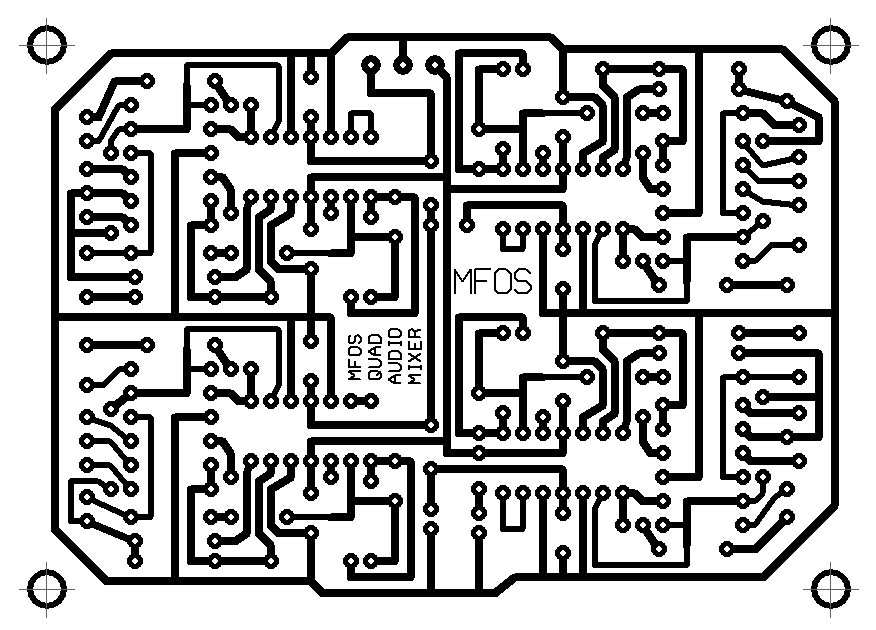
Bottom Copper X2
As viewed from the bottom of the PC board.
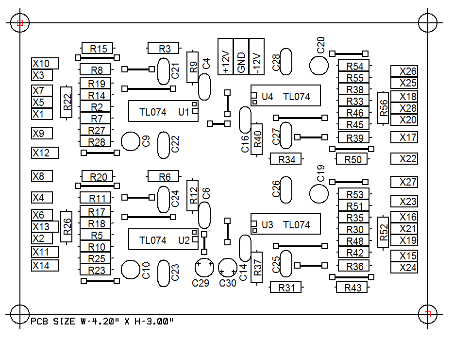
Silk Screen X2
As viewed from the top of the PC board.
- All jumper indicators must be shorted with number 22 AWG solid wire or equivalent.
Front Panel Information
Suggested Front Panel Layout
View as PDF
![]()
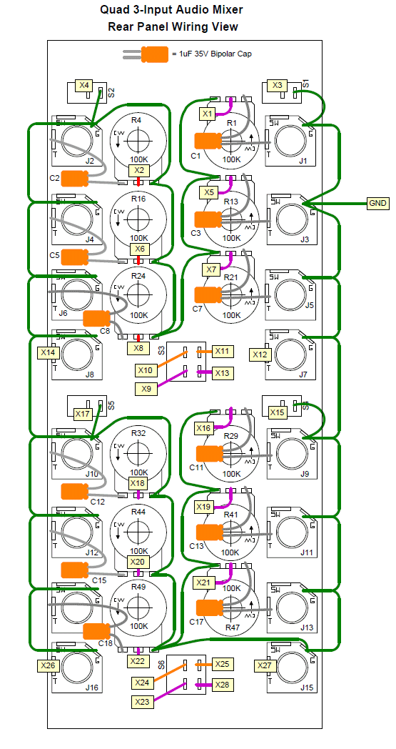
Suggested Front Panel Wiring Diagram
View as PDF
MFOS Quad 3 Input Audio Mixer Project Parts List
Component Notes
All cap voltages should be 35V or more. All resistors are 1/4W 5% (1% will work fine). MFOS PC boards use dual inline IC packages. MFOS PC boards usually use 5mm (0.2") cap lead spacing unless it is obvious from the board's legend that it should be larger or smaller. I often specify axial leads for any caps mounted on the front panel but you can use radial as well by adding some wire to the leads.
Project Parts List
| Qty. | Description | Value | Designators |
|---|---|---|---|
| 4 | TL074 Quad Op Amp | TL074 | U1, U2, U3, U4 |
| 12 | Potentiometer | 100K | R1, R4, R13, R16, R21, R24, R29, R32, R41, R44, R47, R49 |
| 24 | Resistor 1/4 Watt 5% | 100K | R3, R6, R9, R12, R15, R18, R22, R23, R25, R26, R27, R28, R31, R34, R37, R40, R43, R46, R51, R52, R53, R54, R55, R56 |
| 4 | Resistor 1/4 Watt 5% | 20K | R2, R5, R30, R33 |
| 4 | Resistor 1/4 Watt 5% | 2K | R8, R11, R36, R39 |
| 8 | Resistor 1/4 Watt 5% | 33K | R14, R17, R19, R20, R42, R45, R48, R50 |
| 4 | Resistor 1/4 Watt 5% | 470K | R7, R10, R35, R38 |
| 4 | Capacitor Aluminum Bipolar (non polarized) | 10uF | C9, C10, C19, C20 |
| 12 | Capacitor Aluminum Bipolar (non polarized) | 1uF | C1, C2, C3, C5, C7, C8, C11, C12, C13, C15, C17, C18 |
| 8 | Capacitor Ceramic | .1uF | C21, C22, C23, C24, C25, C26, C27, C28 |
| 4 | Capacitor Ceramic | 47pF | C4, C6, C14, C16 |
| 2 | Capacitor Electrolytic | 10uF | C29, C30 |
| 2 | Switch DPST | DPST | S3, S6 |
| 4 | Switch SPST | SPST | S1, S2, S4, S5 |
| 16 | 1/4" Phone Jack | . | J1, J2, J3, J4, J5, J6, J7, J8, J9, J10, J11, J12, J13, J14, J15, J16 |