Ray Wilson authored this content while he was actively running MFOS as the founder and resident genius.
We retain the content because it reflects a valuable point of view representing that time and place.
Article by Ray Wilson
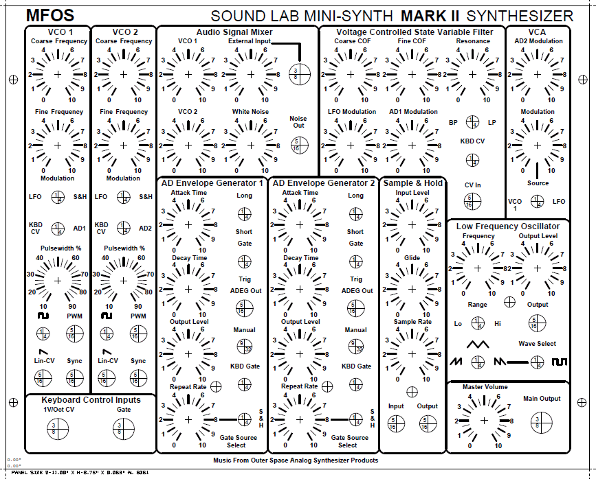
Suggested Front Panel Layout
View as PDFI sell this panel as a 1/16" thick 6061 AL that is 8.75" x 11.0" with screened legend and clear iridite coating.
Panel Dimensions: 8.75 inches x 11.0 inches (222.25 mm x 279.4 mm)

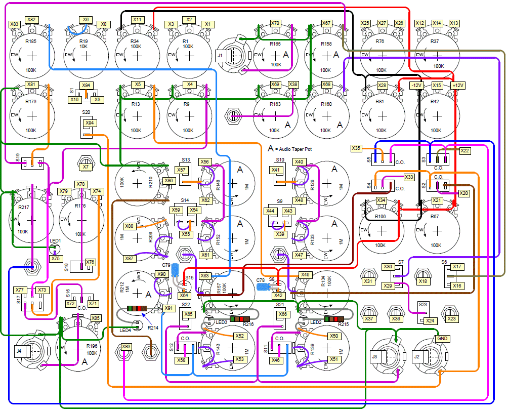
Suggested Front Panel Wiring
View as scalable PDF ...OR... View as One Large ImageWhen viewing the large image (link above) remember that many browsers resize the image to fit in the window initially but also give you ability to zoom to normal size. The large image is 1873 x 1519 pixels. The pdf (link above) allows you to zoom in and not lose resolution so you could also blow the panel drawing up using Adobe Reader and then use the "Snapshot Tool" to copy and paste sections into your image software (including MS Paint or GIMP). If the "Snapshot Tool" is not displayed right click the tool bar and select "More Tools..." and add it to the tool bar.
I suggest that you use your image editing software to make the large image into four 8.5" x 11" quadrants and then print them out (in color if possible) and tape them together so you have a nice large panel wiring guide. It is much easier to see. Most errors result from missing a wire or a ground connection. Take your time and work deliberately when wiring the panel. It is easy to mis-route a wire so... use some different colored highlighters and carefully mark the wire you are currently running, then after you install it check it against the drawing again and if correct mark it with the other color so you know it is run and run correctly. The amount of care you use is directly proportional to the level of success you will achieve. I wired mine from this same diagram and got it right the first time (not always the case but I really took my time and was very careful).
