Ray Wilson authored this content while he was actively running MFOS as the founder and resident genius.
We retain the content because it reflects a valuable point of view representing that time and place.
Article by Ray Wilson
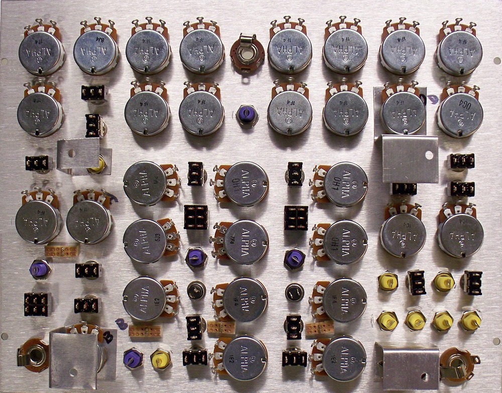
Panel Back Components Installed Pre-Wiring
View Larger ImageWhen I start working on the panel I first mount all of the components by following the wiring guide. I install the banana jacks then the pots then the 1/4" jacks and other components. I mount the LEDs last. The technique I use for mounting LEDs is as follows. I trim a small piece of pre-drilled perf board with copper pads into a small rectangle. The idea is to have perf board "ears" on either side of the LED after it is soldered to the small rectangle of perf board. I then cut double sided foam tape (the stuff that sticks forever) into small squares that I apply to the perf board on both sides of the LED (on the perfboard "ears"). I use a double stack of the foam tape so that the LED sticks through the panel less (you could go three layers if you want). I then push the LED through the panel and the double stick tape holds it in place. I leave the LED leads long so I can solder to them. If you trim them prior to wiring the panel to the PCB BE SURE TO LEAVE THE ANODE LEAD LONGER THAN THE KATHODE so you can tell them apart. I usually trim them when the intra-panel wiring is done.
I fabricated the brackets that hold the PC board from 1/32" thick aluminum sheet (sold in most hardwares). I did it kind of off the cuff and did not measure each one (I only made sure they were the same height) so I don't have any drawings or measurements to share but you get the idea. The only things to keep in mind is that they can't interfere with the wiring or other component mounting. I used the components themselves to mount the brackets so I wouldn't have to drill more holes in the panel.
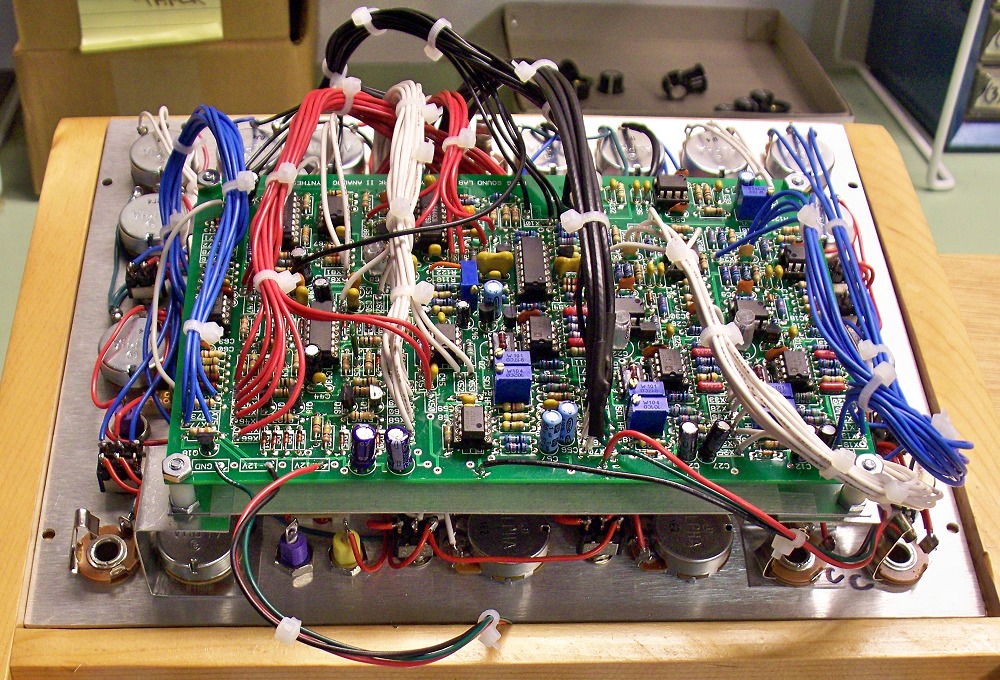
Panel Back Components Installed Post-Wiring
View Larger ImageI use a 22 or 24 gauge stranded wire for both the intra-panel wiring and the connection between the panel and PCB. It is very important to emphasize that the purpose of the wiring diagram is to show what connects to what on the front panel. In many instances on the diagram the wires are shown exploded so you can see all of them. However, while following the diagram regarding what connects to what you should try to run the wires over the shortest possible distance in practice.
Forgive the obvious photo-shop of the capacitors across the manual gate pushbuttons but I didn't want you to forget that they, C78 and C79 1uF non-polarized aluminum caps, get mounted right on the switch terminals of S8 and S15 respectively. They are not shown in the large image. During testing I discovered that without them the manual gate pushbutton was bouncy. I was glad it was such an easy fix.
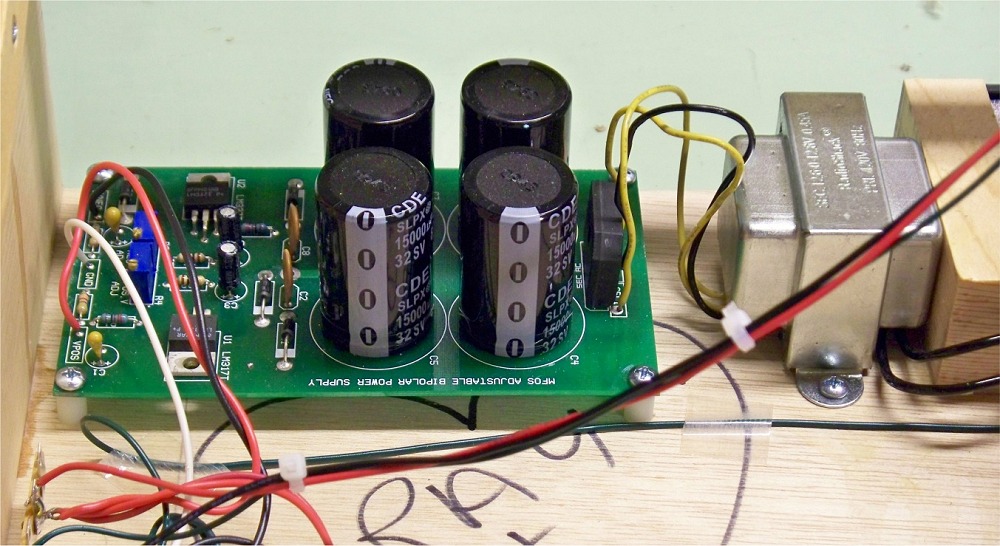
Power Supply (MFOS Adjustable LM317/LM337 1.5A Supply)
View Larger ImageI used the MFOS Adjustable LM317/LM337 1.5A Supply in my unit and to be honest it's a bit of overkill. I left the unit on all night during some testing and the un-heatsinked regulators hardly got warm. When I make my next module cabinet I'll swap out this supply for the MFOS Wall Wart supply.
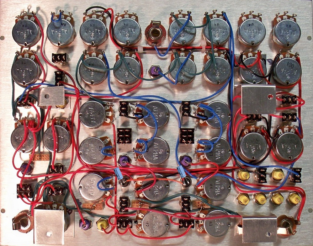
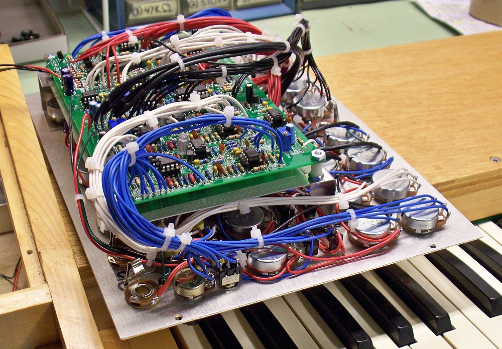
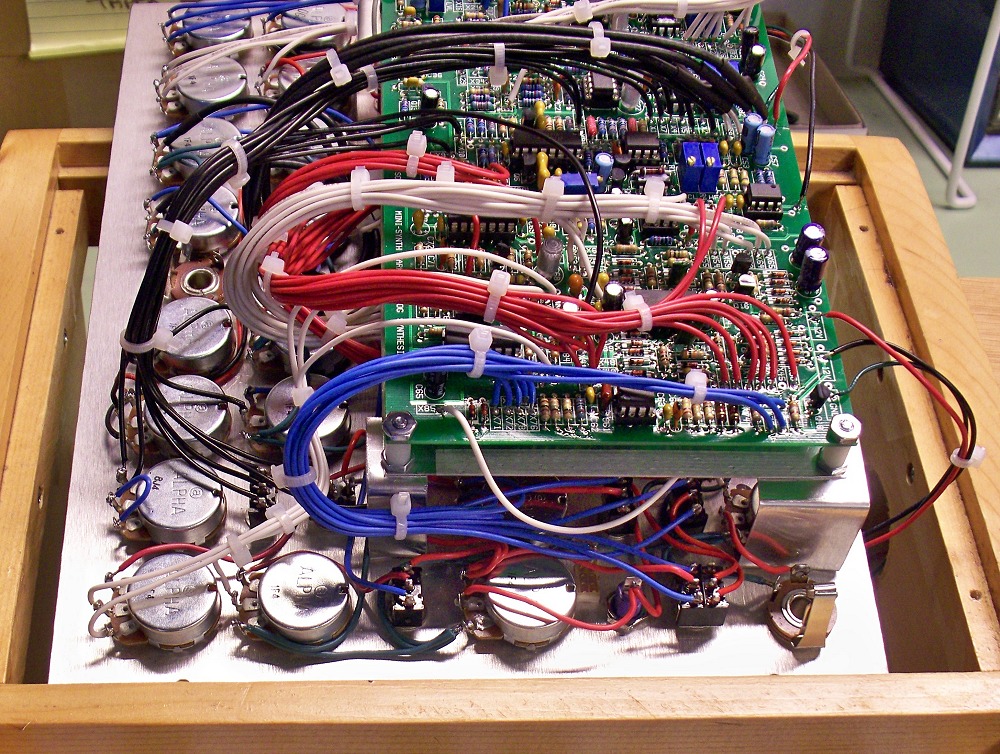
Populated Panel View 1
View Larger ImageAfter I had the intra-panel wiring done I soldered a length of wire to each panel component connection point (the Xn points on the panel wiring diagram) that needed to go to the PC board. I made them long enough to comfortably route to the PC board after it was mounted (plus a safety factor of a few inches). I used colored stickers from an office supply store on each wire and marked the free end with it's Xn designator. I loosely bundled the labeled wires for each module to keep them organized. Once each of the connection points had it's labeled wire soldered to it I mounted the PC board to the supports on the panel. You can see in the photos that I mounted a piece of 1/32" thick aluminum plate the same size as the PC board to the supports and used 3/8" stand-offs to separate the PC board from the plate. I then patiently trimmed and stripped each wire and soldered it to the PC board at the appropriate Xn connection point from the top side of the mounted PC board (one module at a time to stay organized). While doing this strip enough insulation so that the stripped wire protrudes about 1/32" to 1/16" through the bottom but also has about 1/16" of an inch of stripped stranded wire on top so you can get the tip of your soldering iron on it and the pad's top anular ring. Apply your iron to the junction of the wire and anular ring, feed in some thin solder and voila it's nicely soldered. Don't over solder and don't let the stripped wire protrude too far out of the holes on the bottom of the PCB or they may short. Check them over and trim any that appear to long. Try to route the wires so that you can fold the wired board away from the panel on one side in case you need to modify or repair the unit later. After testing you can use wire ties to give the wiring a nice clean organized appearance.
For the mixer connections I used coax wire to reduce extraneous signal reflection into the mixer. Note that I only connect the shield on one side (the board side). For the panel side I strip a half inch or so of the outer insulation off of the coax and then trim the shield close to the outer insulation and put a piece of heat shrink tubing over the area where the inner conductor enters the trimmed shield and outer insulation. This keeps the thin braided shield wires from possibly contacting something they shouldn't.
On the board side I strip the coax, unweave the shield, bend it back away from the center conductor and twist it to get it organized. Not too tight or you may melt the center conductor's insulation in the next step. I then solder a piece of 22 gauge wire to the bent back twisted shield wire so that the solder connection lays against the outer insulation. I then put a piece of heat shrink tubing over the soldered connection so that the center conductor and the soldered on piece of insulated stranded wire stick out of it but the soldered connection of the wire to the twisted shield strands is covered. Now I can solder the center conductor into the appropriate point on the PCB and solder the attached ground wire into the strip of ground connections next to the mixer input connection points. This makes for a trouble free (short free) connection of coax to the board. This is most clearly seen in the links for the larger photos.
I am now sold on this technique of mounting the board to the panel and keeping all of the wiring right there. This is opposed to mounting the board in the case and then running the connecting wires from the panel to the case mounted board. Both methods work but I like only having to run the power connections from the whole assembly to the power supply.
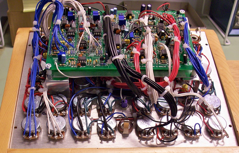
Populated Panel View 2
View Larger ImageAnother view. You may notice that since I used the second prototype PC board (the third board revision became the production version) I did not have a trimmer for R118 so I had to glue a trimmer to the board sideways and run wires from it to the appropriate points on the PC board. The production boards have the R118 legend and mounting pads.
Populated Panel View 3
View Larger ImageAnother view...
Populated Panel View 4
View Larger ImageAnother view...