Ray Wilson authored this content while he was actively running MFOS as the founder and resident genius.
We retain the content because it reflects a valuable point of view representing that time and place.
Article by Ray Wilson
Table of Contents
- LFO Modification
- VCO Modulation Modifications
- Sound Lab Mark II Auxiliary Patch Panel
- Adding More Control Voltage Inputs
- Accessing the Raw VCO Outputs (Switch Selectable)
- Accessing the Raw VCO Outputs (Individual Outputs)
- Accessing the Raw Mixer Output
- Suggested Sound Lab Mark II Auxiliary Panel
- Suggested Sound Lab Mark II Auxiliary Panel Wiring
LFO Optional Modification
Back to TopThe LFO has Ramp, Sawtooth, Triangle and Square wave outputs but when you select Ramp or Sawtooth the period of the oscillation is cut in half due to the diode (D22 or D23) that is put into the circuit effectively cutting off one or the other side of the Triangle waveform. I planned ahead for this optional improvement by putting two pads on the PC board close to U13. These pads are for wires that go to a switching arrangement that puts a .022uF cap in parallel with the C61 (.022uF LFO integrator cap) but only when Sawtooth or Ramp wave output is selected. With this modification the period of oscillation for the LFO is the same for all waveforms. This mod requires that switch S16 be changed to a DPDT Center Off toggle switch (it was formerly a SPDT Center Off toggle switch) and S17 be changed to a 3PDT toggle switch (it was formerly a DPDT toggle switch). As you can see from the modified schematic below that when Square wave is selected the capacitor is effectively out of the circuit. When ramps are selected the capacitor is in the circuit if either non-center position of switch S16 is selected. Thus when Ramp or Sawtooth wave output is selected the added .022uF cap is placed in parallel with C61 and even though we trim off half of the triangle because of the fast charge or discharge times that result with either D22 or D23 in the circuit we have caused these waveforms to take twice as long as they formerly did making the period the same as the Square or Triangle wave outputs.
LFO Optional Modification Panel Wiring
The points XAA and XBB are not screened on the PCB but the extra pads for this mod are identified below. This panel wiring view should be considered a piece of the main panel wiring view. In both switch replacements the additional toggle switch terminals are used to add the Ramp and Sawtooth period modification. The other toggle switch terminals should be wired to the same points shown in the complete panel wiring diagram.
LFO Optional Modification PCB Pads to Use
These are the PCB pads that correspond to the points XAA and XBB. They get wired to the panel as shown above. There are no silk screened legends for these points on the PC board.
LFO Optional Modification Schematic
Here is a schematic showing how the LFO modification fits into the original circuit. Notice that the switches S16 and S17 have changed. Switch S16 is changed to a DPDT Center Off toggle switch (formerly a SPDT Center Off toggle switch) and S17 is changed to a 3PDT toggle switch (formerly a DPDT toggle switch).
VCO1 Optional Modifications
Back to TopFor VCO1 optional modification option 1 you only need a small sized 100K linear pot. For VCO1 optional modification option 2 or 3 you need a small size 100K linear pot with a DPDT switch attached to it. Mouser sells an Alpha pot with an attached DPDT switch that is perfect for this application. Alpha 100K linear pot with DPDT switch.
The small style pot is perfect for replacing the banana jack that was used as the Lin CV input to oscillator 1. Be sure to orient it so that it does not interefere with the panel to case mounting.
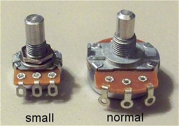
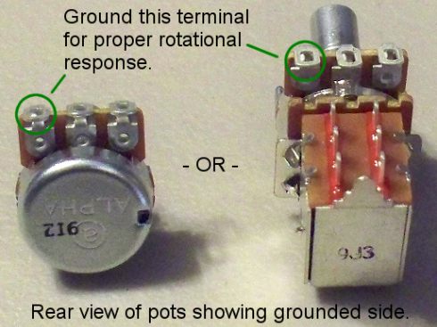
| This is the small 100K linear pot with the DPDT switch attached which you can buy from Mouser. Alpha 100K linear pot with DPDT switch. | This image shows both types of pot from the rear view and displays which side to ground for correct rotational response. |
 |
 |
VCO1 Modification Option 1
This is the simplest modification and it only requires the small linear 100K pot. The Lin CV input banana jack is replaced by the small linear 100K pot and the pot is wired so that the output of the waveform select switch for VCO2 (center pole of S7) is wired to one side of the pot's resistive element, the other side of the resistive element is grounded and the pot's wiper is wired to VCO1 Lin input X23. Make sure to connect the correct side of the pot's resistive element to ground and the other side of it to the center pole of S7 so that the pot responds correctly, i.e. no modulation when the pot is completely counter clockwise (fully off) and full modulation when it is completely clockwise (fully on).
VCO1 Modification Option 2
This modification permits selection of lin or exp modulation of VCO1 by VCO2. The switch from Mouser toggles by being pulled in or out. When the switch is pulled out you get one form of modulation and when you push it in you get the other. Be sure and orient the pot with switch so that it does not interfere with the panel mounting to your case. Also be sure to wire the pot for correct rotational response (ground the correct side of the resistive element).
VCO1 Modification Option 3
This modification permits selection of lin modulation of VCO1 by the LFO or expo modulation of VCO1 by VCO2. When the switch is pulled out you get one form of modulation and when you push it in you get the other. Be sure and orient the pot with switch so that it does not interfere with the panel mounting to your case. Also be sure to wire the pot for correct rotational response (ground the correct side of the resistive element).
Sound Lab Mark II Optional Auxiliary Panel Back to Top
Here you will find information that pertains to using your Sound Lab Mark II with other modular equipment. Perhaps you want some more CV inputs for the VCOs or the VCF or you'd like to access the raw VCO outputs or the raw signal mixer output. All of that is possible so you came to the right place. Read on...
Adding More Control Voltage Inputs
Back to TopIt is important to emphasize that the added summing resistors should be mounted close to the others. As I suggest use either non-conductive epoxy, rubber cement or double stick tape etc. to affix the added resistor to the current ones and connect as explained in the image. How do I know if my epoxy is non-conductive? Make a little pile, let it dry and stick the leads of your ohm meter on it. It should read the same as when they are open.
The wire from the other end can be long (it goes to your jack) but you don't want to stick a long wire on the summing input of the CV summing op amp. Solder the end of the resistor attached to the summing node to the lead of one of the other summing resistors (shown in the highlighted box).
Accessing the Raw VCO Outputs (Switch Selectable)
Back to TopHere are the points on the front panel where you can access the switch selectable outputs of the VCO. You would simply connect the center poles as explained in the illustration to the tip connectors of the jacks of your choice.
Accessing the Raw VCO Outputs (Individual Outputs)
Back to TopHere are the point on the front panel where you can access the individual outputs of the VCO. You would simply connect the outer switch poles as explained in the illustration to the tip connectors of the jacks of your choice. This configuration is shown in the Auxiliary Panel drawings below.
Accessing the Raw Mixer Output
Back to TopHere is the point on the PC board where you can access the raw signal mixer output. You could send this signal to your modular or other processing circuitry. Keep in mind that this is a DC coupled point and if you would prefer to connect via a capacitor I would suggest a 10uF non-polarized (also called bipolar) cap between this point and the tip connector of the jack of your choice.
Suggested Sound Lab Mark II Auxiliary Panel
View as PDF Back to TopThis is just a suggestion for an auxiliary panel for use with the Sound Lab Mark II. This will give you even more options for interconnection between Sound Lab Mark II modules but also allows more flexible use of the Mark II synthesizer with your modular or other MFOS equipment. I find that the passive attenuators always come in handy for setting modulation levels in general.
Suggested Sound Lab Mark II Auxiliary Panel Wiring
View as PDF Back to TopHere is the wiring view of the auxiliary panel. Remember that the resistors DO NOT GET MOUNTED ON THE PANEL. They get mounted on the PC Board as explained in the illustration above. At the risk of being obvious wire the circuit points to the tip connector of whatever type of jack you use. I show banana jacks in the illustration. The ground wire needs to be connected to the power supply ground of the Sound Lab Mark II.