Ray Wilson authored this content while he was actively running MFOS as the founder and resident genius.
We retain the content because it reflects a valuable point of view representing that time and place.
Article by Ray Wilson
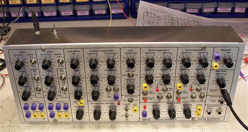
New Sound Lab Mark II 17 x 7 Inch Panel
The new Sound Lab Mark II 17 x 7 inch front panel is finally ready for prime time. This is my documentation verification build and I have to say that other than a few minor bugs this went together really nicely. It is a LOT of wiring and I can't emphasize enough how important it is to take your time and make sure EVERY WIRE is present, accounted for and properly soldered.
Please Read All Sections First - Order and Build Later - You'll Be Glad You Did

It is very important to read over this information prior to ordering a plate kit or trying to build the unit. If you make a wiring error and you don't find it until you have buttoned up the unit you will wish you had paid more attention when you were building. I took several days and checked my work fanatically and I still made an error or two which I had to trouble shoot and fix. The documentation is now correct and verified. I worked from the same documents I am posting here.
Panel Template for Control Legend
This 100% image may still need scaling depending on your drawing program. The horizontal width between the edge targets when printed correctly should be 17". The vertical height between the edge targets when printed correctly should be 7". Printing may require a commercial printer as found at an office supply store or FedEx office center.
This PDF is on a large C sized sheet. You will need a PDF editor to move the drawing to a smaller sheet if desired. Printing may require a commercial printer as found at an office supply store or FedEx office center.
Important Considerations While Building
The first step is to install all of the components to the front panel including the LEDs. I install my LEDs as shown using a small piece of perf board which I double-stick foam tape to the panel with the LED sticking through it's respective hole.If you decide to use LED Clip and Rings (shown below) you will need to drill the LED holes out to the size required by the LED clip.
LED Clip and Ring.
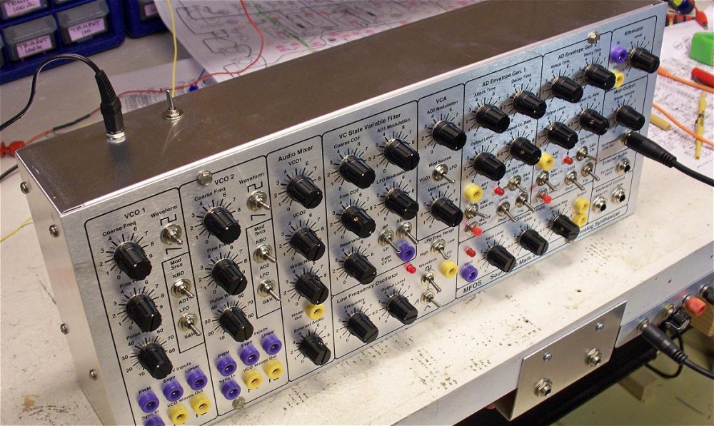
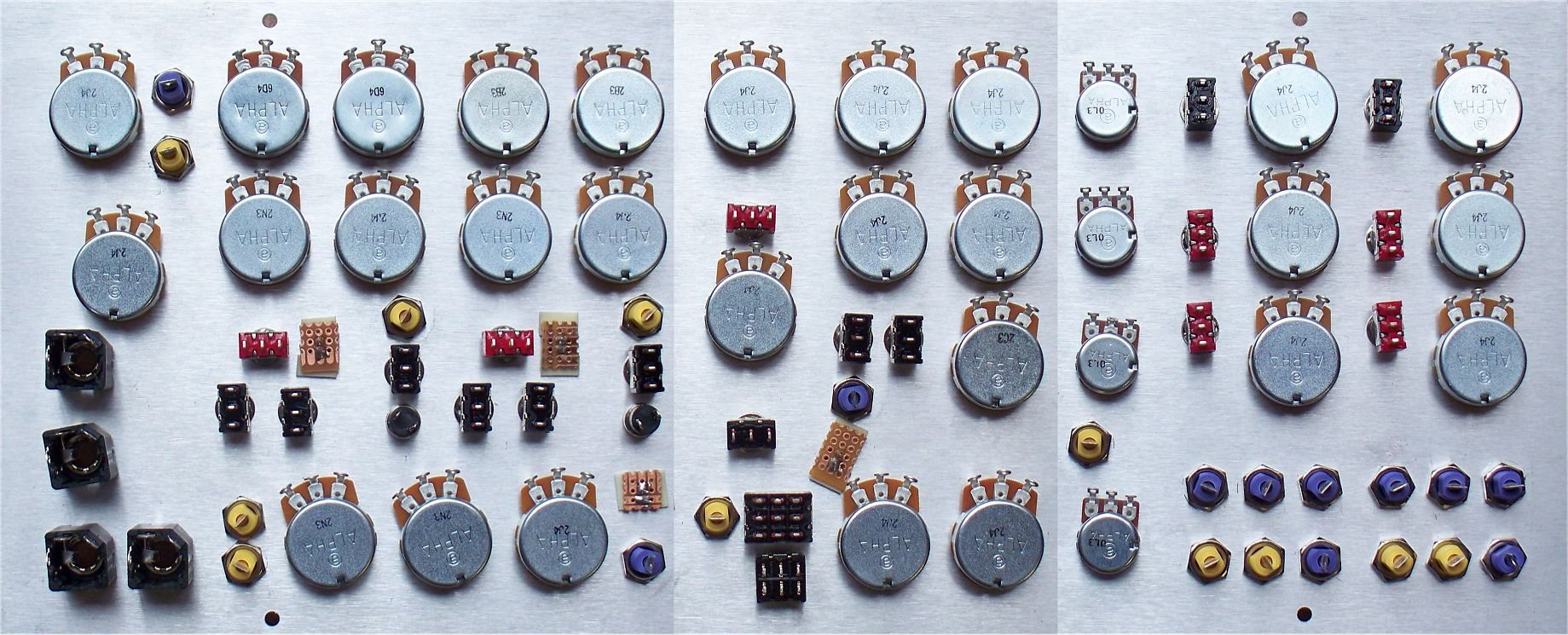
Here is a shot of the wiring diagram and a shot of the panel with the components installed.
Notice that on the wiring diagram the switches that are ON-OFF-ON type (Center Off) are marked as "CO" to remind you. Pots marked with an "A" are ones for which I recommend Audio Taper pots. There is no big issue if all you can find are Linear Taper pots.
Note that S17 becomes a 3PDT (three pole double throw) switch and S16 becomes a DPDT (double pole double throw) center off (ON-OFF-ON) switch. Be sure and order the correct switches for this project. The parts list reflects the original design.
SUPER IMPORTANT NOTES
Note the two colors of wirepoint indicators
Notice the two colors (yellow and pink) of the panel to PC board wirepoint indicators (rectangles with Xn in them) shown in the wiring diagram. Once the intra-panel wiring is done (i.e. the wires between the components on the panel are all soldered) you must add wires with labels on them to the pink wirepoint indicators. These will be connected to the PC board after the PC board holder is mounted. It is not possible to connect the wirepoint indicators shown in pink after mounting the PCB holder and PCB.
Leave service loops (sufficient slack) where needed
It is very important while doing the intra-panel wiring to leave sufficient wire for service loops on the VCO1 Level control (R158), the White Noise Level control (R163) and the AR2 Repeat Gate Rate control (R143). This will facititate the temporary removal of those pots after the intra-panel wiring and the addition of wires with labels for all the pink wirepoint indicators is completed. Those three pots hold the PC board mounting plate to the front panel. Once the PC board mounting plate is mounted the remaining wirepoints can be connected between the panel and the PC board (they are not covered by the PCB mounting plate).
Run Wires With Trouble Shooting In Mind
It is a very good idea to plan to run the wires so that they:
- Avoid the flanges on the PCB mounting plate.
- Don't get knicked or cut on the PCB mounting plate.
- All come out as much as possible on the same side of the mounting plate.
- Have sufficient slack to be able to trouble-shoot the panel and PC board if necessary.
Wiring Diagram PDF - Use CTRL - Mouse Wheel Scroll to Magnify
Two Page Printable Wiring Diagram
Set printer to "fit to page", print out on 8.5 x 11 paper, overlap properly and tape together to produce a nice large printed wiring diagram. If you have access to a color printer - use color.Notice that on the wiring diagram the switches that are ON-OFF-ON type (Center Off) are marked as "CO" to remind you. Pots marked with an "A" are ones for which I recommend Audio Taper pots. There is no big issue if all you can find are Linear Taper pots.
Note that S17 becomes a 3PDT (three pole double throw) switch and S16 becomes a DPDT (double pole double throw) center off (ON-OFF-ON) switch. Be sure and order the correct switches for this project. The parts list reflects the original design.
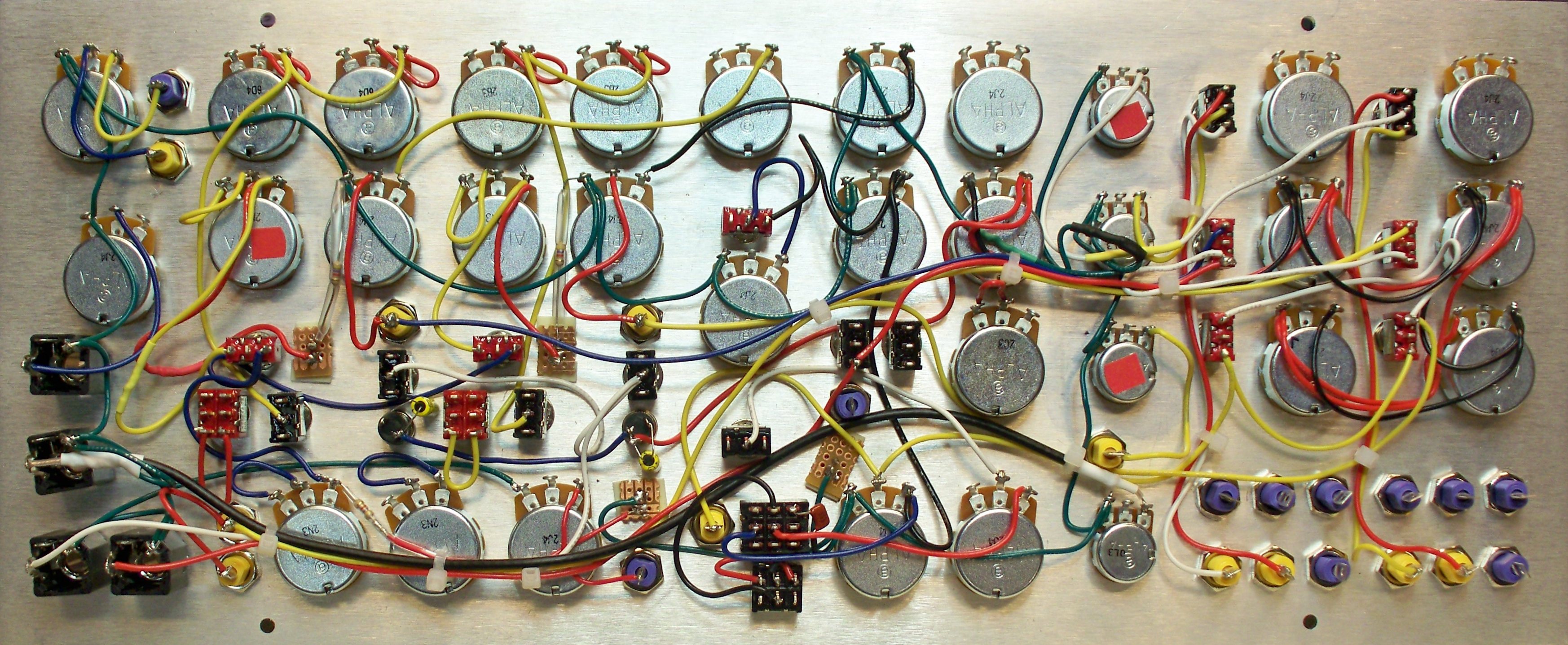
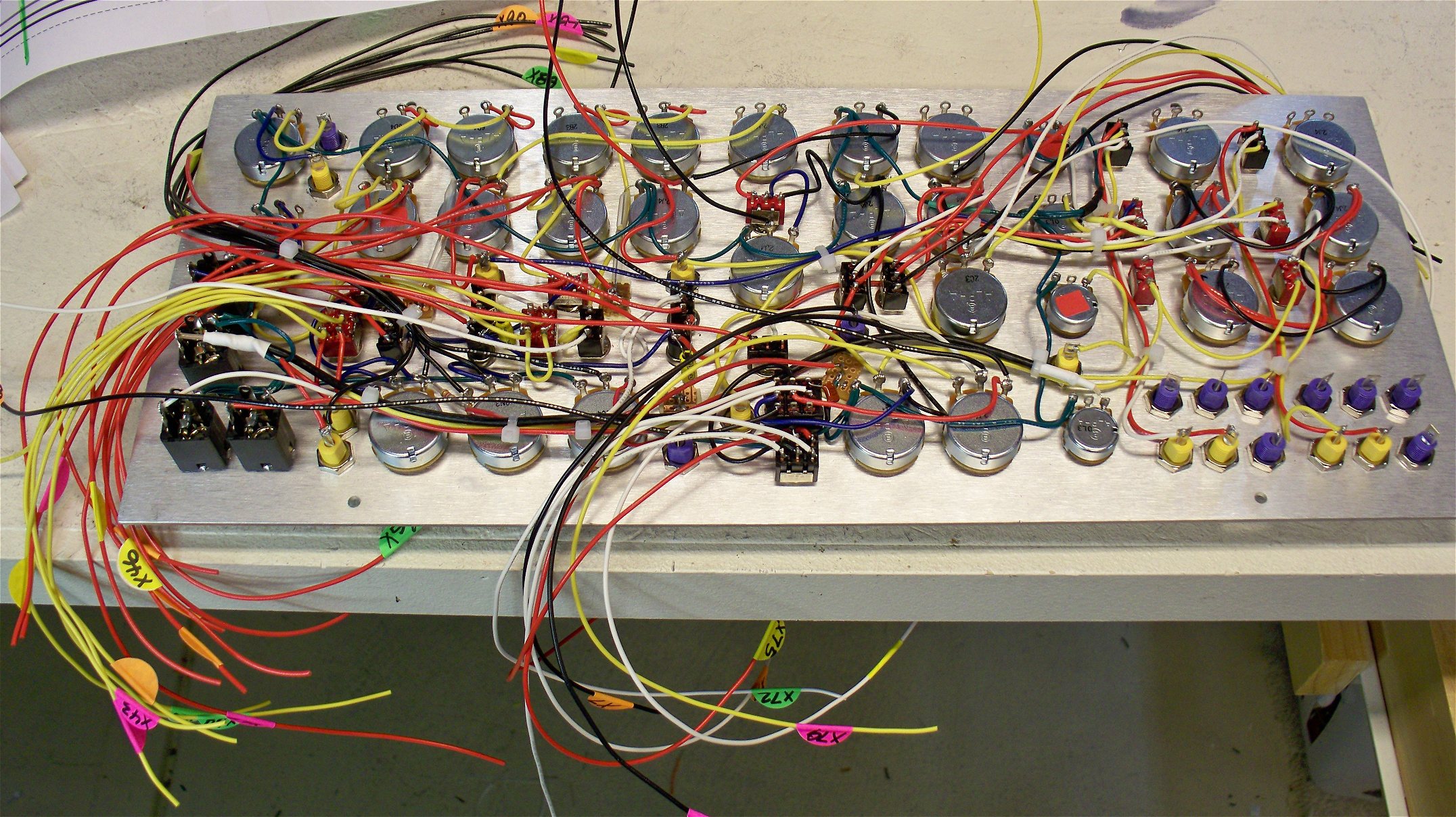
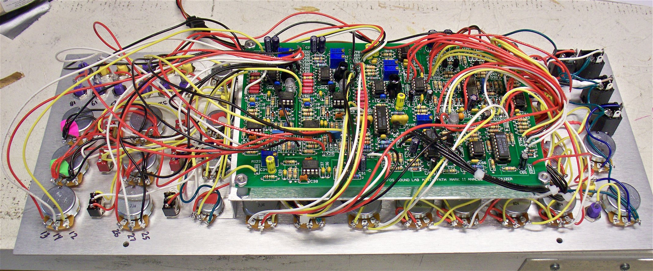
Intra Panel Wiring Completed
The purpose of the wiring diagram is to show what gets connected to what. When doing the actual wiring it is best to keep the wire runs as short as possible. I used stranded 22 AWG wire to do the wire up. Take your time, look over the diagram until you are certain you have every wire run. When a terminal will be used to run a wire to the PC board - DO NOT FILL IT WITH SOLDER leave room for the wire that will go to the PCB later.When the board mounting plate is mounted and the PC board is wired to all of the panel points you will kick yourself if you forget a wire so - TAKE YOUR TIME AND GET IT RIGHT. Triple checking your work or getting another set of eyes on it will definitely pay off later.
Keep inspecting and if any panel component terminal has no wire on it make sure that it only connects back to the PCB on the diagram.
The GROUND connections go all over the panel so make sure they are all present and accounted for. The panel itself gets grounded by means of the 1/4" jack sleeves. Modulator signals show up on several pots and switches as do +12V and -12V. Be EXTRA CAREFUL when routing +12V or -12V wires so that they don't get knicked or shorted to the panel or PCB mounting bracket. Trim the soldered terminal connections to avoid shorts. Use shrink tube to insulate panel mounted resistor or capacitor leads where needed.
This wiring diagram shows the modification added to the LFO which makes all forms of the ramp wave have an equal period. In the original design the ramp and saw waves from the LFO were only half the period of the square and triangle waves. This was because the diodes that change the triangle wave into the ramp and saw shapes would shorten the cycle time by 1/2. With the scheme shown in the wiring diagram and in the modified LFO schematic shown below an extra capacitor is switched into the integrator when the LFO is switched to produce ramp or saw waves. Thus all waveforms have the same period.
The LFO circuit uses two un-marked donuts on the PC board. They are referred to as XAA and XBB. In the circuit they are connected to both sides of C61 (.0022uF capacitor). They are used to switch in an additional .0022uF capacitor to cause the LFO's ramp and sawtooth waves to have the same period as its square and triangular waves.
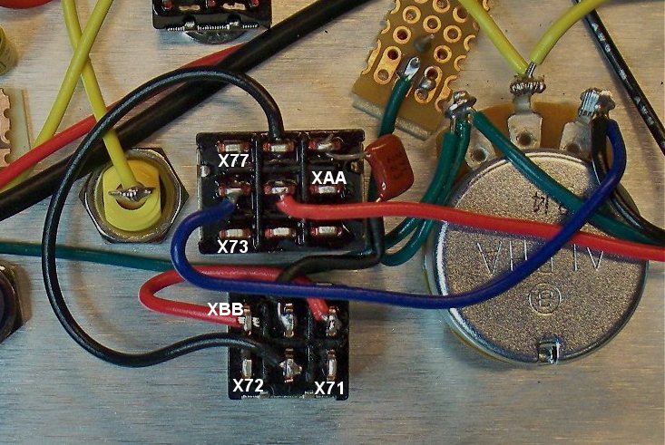
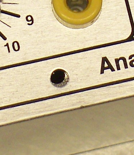
Here are the two donut pads. The image shows which is XAA and which is XBB. they are located next to U13.
This is the schematic of the LFO with the addition of the switching circuitry. Note that S17 becomes a 3PDT (three pole double throw) switch and S16 becomes a DPDT (double pole double throw). Be sure and order the correct switches for this project.
Wires Connected and Labeled That Will Be Underneath the PCB Mounting Bracket
These are the panel to PCB wires which will be located underneath the PCB mounting bracket. You must attach them leaving sufficient slack to connect to the PCB and allow for later removal of the bracket and PCB if necessary. The labels are round self stick Avery labels available at most office supply stores. Again care here is very important so that you don't have to take everything apart later to add a forgotten wire.Keep inspecting the connections which will be under the mounting plate. If any panel component terminal has no wire on it - something is amiss. Find out why as most likely it is a forgotten connection.
PCB Bracket Installed
Hopefully you read EVERYTHING first and have service loops (sufficient slack) for pots R158, R163, and R143 so you can loosen the mounting hardware of each, remove the pots and use them to secure the PCB mounting bracket to the front panel. Attach the fully populated PCB to the mounting bracket before installing the bracket.
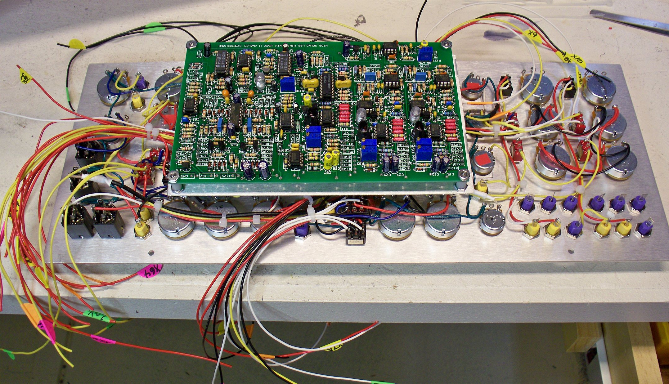
Connect Wires To PCB
Take your time and solder the wires to the PCB being careful to connect the wires to the correct donuts on the PCB. Soldering from the top of the board is not difficult but you need a soldering iron with a fairly sharp tip. After you trim the wire (leaving some slack for disassembly if needed) strip about 1/8" of insulation from the end and insert it into the donut leaving a 1/16" or so of the stripped wire above the top donut. Place your clean tinned soldering iron tip at the junction of the bare wire and the top donut as you feed in some thin solder. The solder will melt and flow around the wire and into the hole - don't turn it into a blob of solder - you'll see when the top fillet looks sufficient. I work under a magnifier because I don't have superman eyes. I suggest you give it a try. If you apply too much solder use solder braid to clean up and reflow the joint.
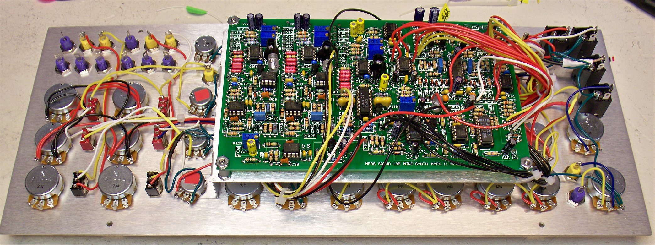
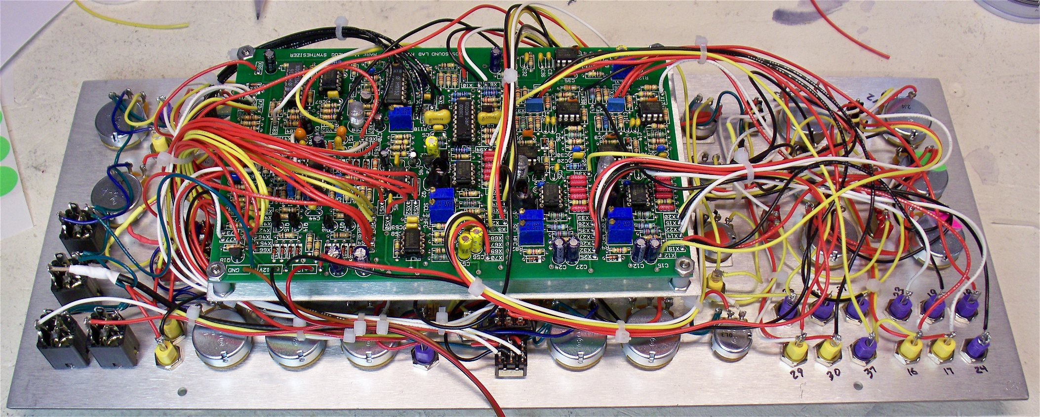
Connect The Remaining Wires To PCB
Again, take your time and solder the wires to the PCB being careful to connect the wires to the correct donuts on the PCB. Solder from the top of the board. You can see that I left a lot of slack. Once testing is complete I will use some wire ties to contain the rat's nest a bit.
Testing Completed - Corral The Wires a Bit
After testing I corraled the wires with a few wire ties. I flattened the wires on the VCO controls side as much as I could to accomodate the MFOS Wall Wart power supply I used to power the unit.While testing I discovered a bug or two which were related to wrong component values - yes even I who designed this thing put a couple of 10K resistors where 47Ks were supposed to go. I also discovered two sets of panel connections that were reversed. I also changed a couple of resistor values to lower the range of my VCOs. The VCO coarse adjustment was going from about 20 Hz (fully CCW) to about 37KHz (fully CW) and I changed that so that they go from sub-audible (about a cycle per second or so) to about 20KHz. If you want the same range change R36 and R75 from 39K to 2K.
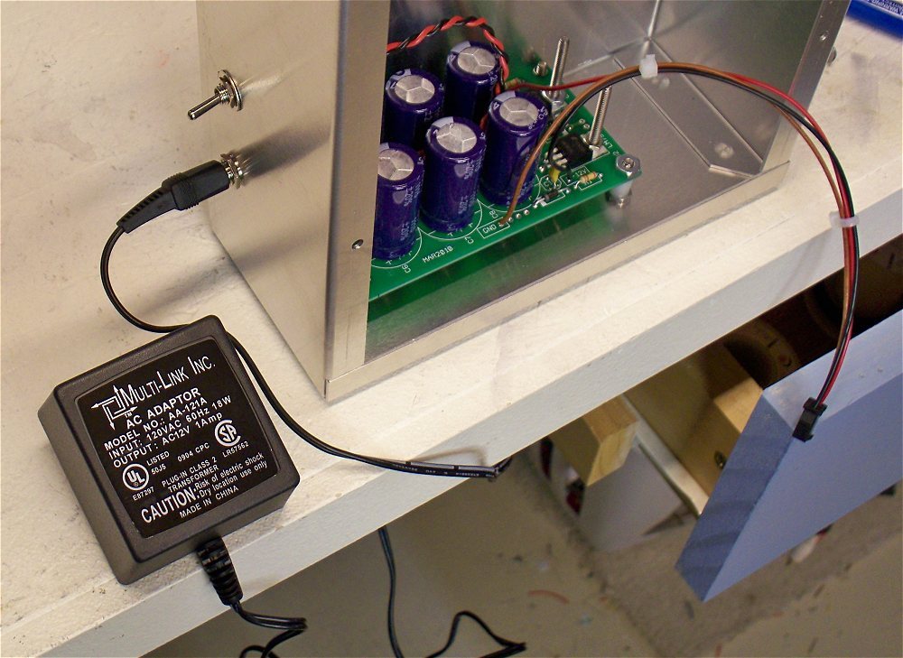
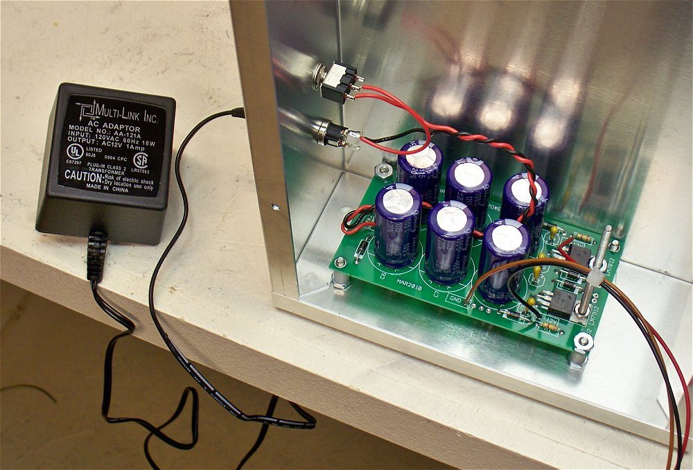
Powering the Unit With the MFOS Wall Wart Supply
I really like the MFOS Wall Wart Supply and it powers this synth perfectly with power to spare. If you use the same idea make sure you don't mount the supply too close to the bottom or you'll have a hard time tightening the mounting hardware. However be sure and mount it far enough into the case so that the VCO pots don't impinge on the supply's capacitors. I added a power switch to switch the wall wart's power to the supply PCB. Although the power jack is isolated from the case via phenolic components I highly suggest that you connect the jack's shell connection to the side of the input voltage that becomes the ground of the supply. This means connect the WW2 donut to the shell terminal of the power jack. Connect WW1 to the power jack's center terminal. The two long screws I used to mount the regulators to the PCB act as heat sinks. The regulators are practically coasting due to the low power draw of the Sound Lab Mark II.
Mounting in BUD Box AC-423
Again I really tried to make sure the holes lined up - panel to BUD box - and I got pretty close but not exactly right on. However the panel mounted to the BUD box with sheet metal screws just fine. The box has some flex and it was very easy to get the front mounted despite my ineptitude at locating the plate's mounting holes.
Voila... Now It's Fun Time!
I'm really happy with the results and the synth tuned up very nicely during calibration. This is the fourth time I've built a Sound Lab Mark II now. I think this may be the final unit. Phew...!