Article by Ray Wilson
Introduction
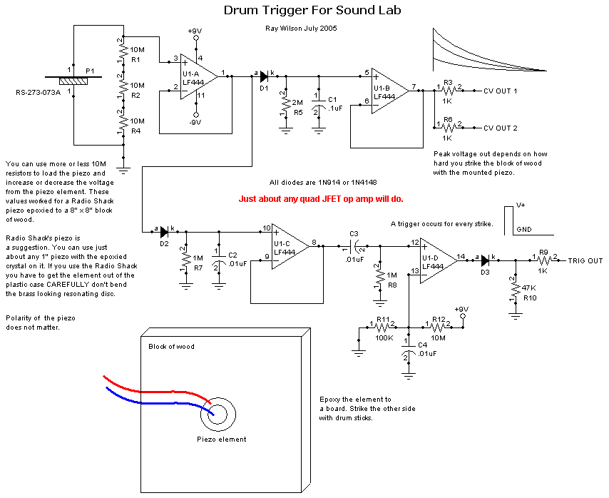
Turn your Sound Lab into an electronic drum with this simple circuit. The output of this circuit is dynamic in that it puts out a voltage that is relative to the force with which you strike the drum pad. It also puts out a trigger useful for turning on the Sound Lab AR generator.In the samples recorded with Cakewalk I have three tracks. One with a drum loop, one with Sound Lab with the CV out of the circuit and one with Sound Lab noise triggered by the circuit. The third sample is just banging on the drum pad to demo the dynamic CV output.
Sample MP3 wet with a drum beat Sample MP3 dry with a drum beat Sample of dynamic CV output.Charles Osthelder Wrote a Cool Article About Electronic Bongos
Charles includes some helpful tips, great plans and a PC Layout in these PDFs!
Circuit Description
Here is how it works.The piezo electric effect is the property of quartz (and other crystals) to develop an electromotive force or voltage across opposite faces when subjected to tension or compression, and, conversely, to expand or contract in size when subjected to an electromotive force. In this circuit we are interested in the former effect. When you bang on a crystal it emits a voltage.
Banging on a board that has the piezo attached to it will cause the piezo to emit a voltage that corresponds to the vibration of the board. Sort of a sine wave that starts at a high amplitude and then rapidly decays in amplitude as the board stops vibrating. I suggest epoxying the piezo in the middle of a piece of wood. I used a 3/4 inch thick block of pine 8" x 8" which works admirably. Strain relieve the wires and solder some stronger ones to the piezo's leads so you don't inadvertently pull the wires off of your piezo.
The circuit loads the piezo with several 10 Meg resistors to reduce the voltage it can emit and buffer its output voltage with an op amp (U1-A). The above ground excursions of the buffered signal charge C1 via D1. The voltage on C1 is dependent on how hard you hit the board with the piezo mounted on it (we will call this the drum pad from now on). The voltage on C1 is drained away by R5. You can change how quickly or slowly the voltage decays off of C1 by changing the value of R5. Higher value longer decay, lower value faster decay. This voltage envelope is buffered by U1-B which feed the CV OUT 1 and 2.
A second similar circuit (D2, R7, C2, and U1-C) also allows the positive excursions of U1-A to charge C2 and deliver the much faster envelope to the input of U1-D via C3. U1-D acts as a comparator and goes high when its input sees a voltage above 90 mV. The above ground excursion of U1-D is fed via D3 and dropped on R10. The trigger is fed out via current limiter R9 1K resistor.
The triggers are fairly responsive. It is important that you have changed the value of C2 in the Sound Lab to .001uF so that the circuit can be triggered more rapidly. When you strike the drum pad with moderate force you will always get a trigger. Striking harder will cause the output CV voltage to go higher.
Its pretty darn cool and fun to play with.
Sound Lab Mini-Synth Drum Trigger [Schematic PDF]

Sound Lab Mini-Synth Drum Trigger Parts List
| Qty. | Description | Value | Designators |
|---|---|---|---|
| 3 | 1N914 Sw. Diode(s) | 1N914 | D1, D2, D3 |
| 3 | Ceramic Capacitor (S)(s) | .01uF | C3, C2, C4 |
| 1 | Ceramic Capacitor (S) | .1uF | C1 |
| 1 | LF444 Quad Op Amp | LF444 | U1 |
| 1 | Radio Shack Piezo Element 273 | RS-273-073A | P1 |
| 1 | Resistor 1/4 Watt 5% | 100K | R11 |
| 4 | Resistor 1/4 Watt 5%(s) | 10M | R1, R4, R2, R12 |
| 3 | Resistor 1/4 Watt 5%(s) | 1K | R3, R9, R6 |
| 2 | Resistor 1/4 Watt 5%(s) | 1M | R7, R8 |
| 1 | Resistor 1/4 Watt 5% | 2M | R5 |
| 1 | Resistor 1/4 Watt 5% | 47K | R10 |