Ray Wilson authored this content while he was actively running MFOS as the founder and resident genius.
We retain the content because it reflects a valuable point of view representing that time and place.
Article by Ray Wilson
PC Board Parts Layout Illustrations
If you start to see the sample and hold clock stop working when setting the pot to lower settings I recommend that you change C64 (2.2uF Tantalum Capacitor) to a 2.2uF non-polarized aluminum capacitor. Even though the voltage on C64 oscillates about ground it spends a majority of its time between ground and -2.5 volts. This results in C64 becoming leaky and preventing the sample clock oscillator from oscillating at lower settings. The part list has been updated to reflect this.
If you start to see the repeat gate stop working when setting the pot to lower settings I recommend that you change C69 (10uF Tantalum Capacitor) to a 10uF non-polarized aluminum capacitor. The voltage on C69 oscillates about ground which causes C69 to see negative voltage about 50% of the time. This results in C69 becoming leaky and preventing the repeat gate oscillator from oscillating at lower settings. The part list has been updated to reflect this.
THE PC BOARD LEGENDS FOR C64 and C69 HAVE POLARITY MARKINGS. IGNORE THEM WHEN INSTALLING THE NEW NON-POLARIZED CAPS
| IMPORTANT INFORMATION ABOUT TEMPCO INSTALLATION | ||||||||
|
||||||||
|
|
||||||||
| Using Two Discrete Transistors Instead Of SSM2210 | ||||||||
|
Just to reiterate you can use 2 non-matched transistors just to get the oscillators going but you need matched
transistors in order for the ULTIMATE's VCOs to track 1V/octave accurately.
When using two discrete NPN transistors (matched or unmatched)
in place of the SSM2210 you just insert them onto the PC board
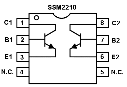
in the holes where the SSM2210 chips would have gone. As you can see from the diagram below the SSM2210
chip contains two NPN transistors. One is connected to pins 1 (collector), 2 (base) and 3 (emitter) and the
other is connected to pins 6 (emitter), 7 (base), and 8 (collector).
Pins 4 and 5 are not connected (N.C.). Thus if you use discrete transistors instead (2N3904 or 2N2222) just
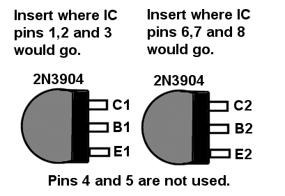
insert them into the holes where the SSM2210 IC would have been mounted. One of the transistors will go into
the holes for SSM2210 pins 1 (collector), 2 (base) and 3 (emitter) and the other will go into
the holes for SSM2210 pins 8 (collector), 7 (base) and 6 (emitter). Nothing goes into the holes for pins 4 and 5.
Simply do the same thing for each SSM2210 you replace with discrete transistors.
NOTE! You can insert the pins of the two discrete transistors into the appropriate pins of the 8 pin socket that fits in the space for the SSM2210 instead of soldering them if it is a high quality socket with machined pins. While the less expensive sockets work adequately with ICs (though I always use machined sockets) I would not trust the connection with transistor pins and would solder them directly into to the board rather than use the sockets. Attach an aluminum spring clip heat sink to each lead as you solder it when using matched discrete transistors to avoid changing their characteristics with overheating.
|
||||||||
|
|
||||||||
| PC Board Module Map | ||||||||
|
This view shows the locations of the various modules on the PC board. While doing some troubleshooting
recently I found out first hand that this is a handy thing to have.
|
||||||||
 |
||||||||
|
|
||||||||
| PC Board Part Designators View Larger Image | ||||||||
 |
||||||||
|
|
||||||||
| PC Board Part Values View Larger Image | ||||||||
|
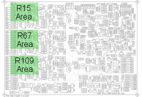
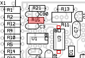
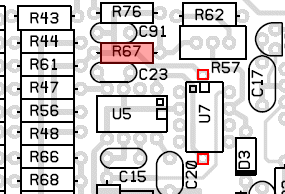
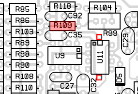
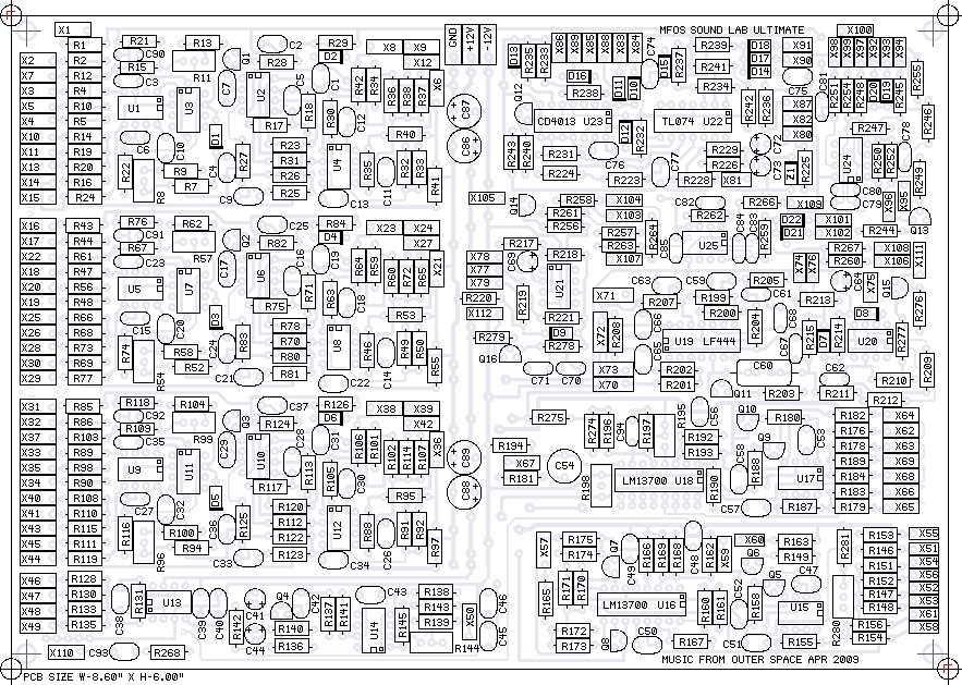
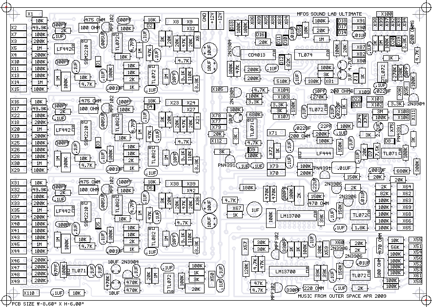
Notice that you do not install resistors: R118, R76, or R21 shown in the designator view above. These designators
are simply not used. This view is VERY HANDY while populating the PC board. The PDF can be printed and used for a bench reference.
The large size image can be printed in pieces by dividing it in your paint program and perhaps printing the board as
four separate quadrants.
|
||||||||
 |
||||||||
|
|
||||||||
| PC Board Silk Screen View For Reference | ||||||||
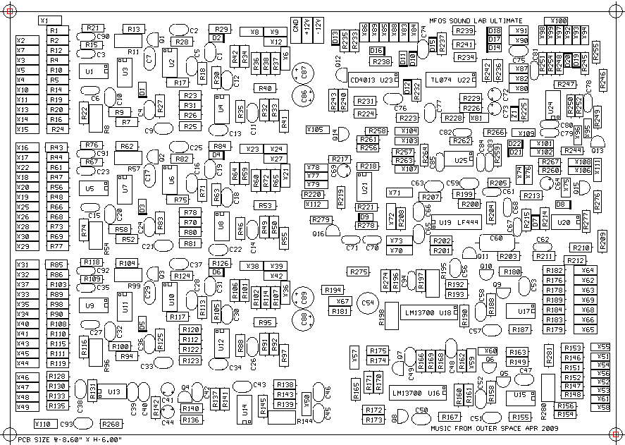 |
||||||||
|
|
||||||||
| PC Board Top Copper View For Reference | ||||||||
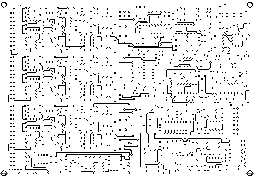 |
||||||||
|
|
||||||||
| PC Board Bottom Copper View For Reference | ||||||||
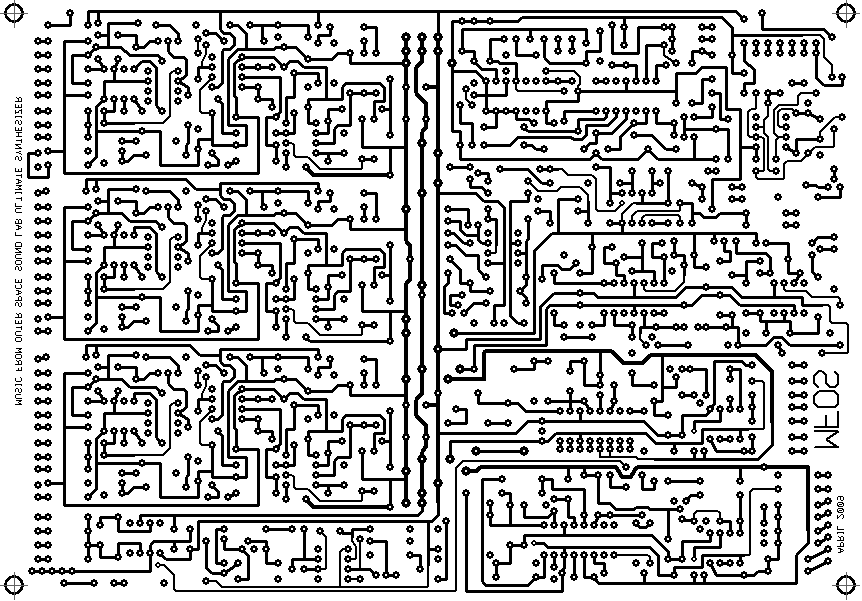 |
||||||||
|
|
