Ray Wilson authored this content while he was actively running MFOS as the founder and resident genius.
We retain the content because it reflects a valuable point of view representing that time and place.
Article by Ray Wilson
| Planning to build the ULTIMATE EXPANDER? You will need to do this simple mod to your ULTIMATE to get the most out of the EXPANDER. It is really simple but be careful, take your time, read over the entire page first to familiarize yourself with the mod. If you have any questions or something is unclear email me and I'll be happy to help. Go to the ULTIMATE EXPANDER website... | |
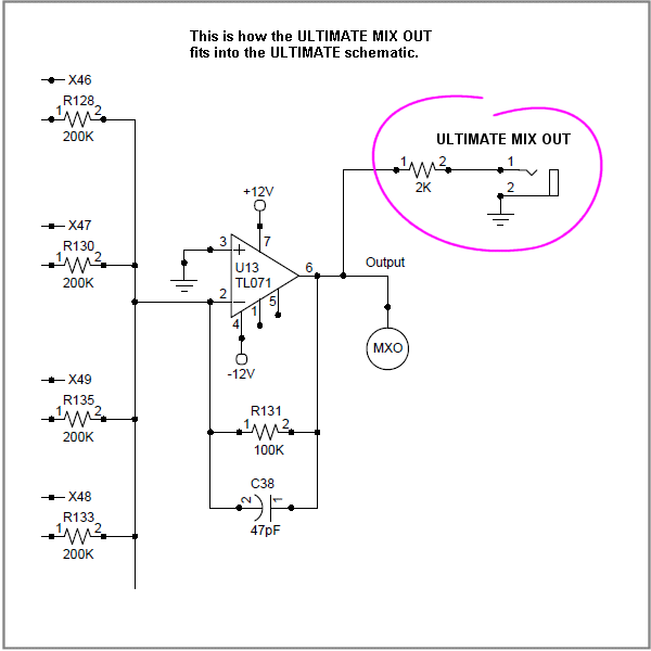
| ULTIMATE MIX OUT Schematic
This is all there is to connecting the mixer out to the ULTIMATE MIX OUT jack. It is simply the output of the ULTIMATE's signal mixer connected to a 1/4" jack with a 2K resistor in series. The 2K resistor is actually optional but it keeps the ULTIMATE's mixer from going quiet while you connect a cable between the ULTIMATE and the ULTIMATE EXPANDER as the cable's tip touches the EXPANDER's "FROM ULTIMATE MIXER OUT" jack sleeve. I recommend using a 1/2 watt resistor for the greater mechanical strength it provides.
|
|
 |
|
|
|
|
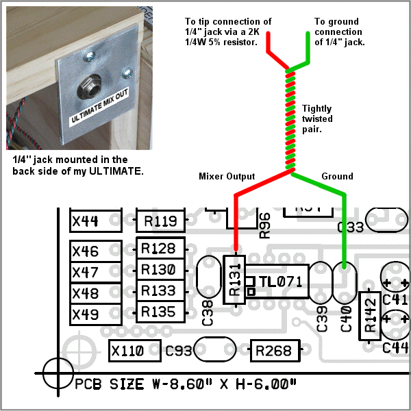
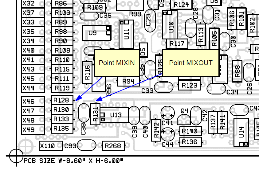
| ULTIMATE MIX OUT PC Board Connection Points
Twist the pair before you connect it to the board. I usually take about twice the length of wire needed and twist one end of the two together a bit. Then I chuck the twisted end into a variable speed drill and grasp the wire between my thumb and forefinger near the chuck and as I slowly rotate the drill I slide my fingers toward the ends opposite the chuck. Don't try to twist the wire to full torsion all at once but do it in stages. Repeatedly grasping the wire near the chuck and sliding toward the ends opposite the chuck. Each time allow the wire to twist more tightly. Don't go too far or you could cause the wires to short as the insulation becomes too compressed. Untwist the ends a bit for connection to the board and the jack. You will connect the hot lead (the one that will go to the 2K resistor and on to the jack tip terminal) to the side of R131 that connects to the output of U13 pin 6. If you have to remove and re-install a new R131 to get enough lead to get the hot lead around R131's lead for a good connection and solder joint it may be a good idea to do so. If you have enough lead already great. You will connect the ground lead (the one that will go to the jack's sleeve) to the side of C40 that connects to ground. If you have to remove and re-install a new C40 to get enough lead to get the ground wire around C40's lead for a good connection and solder joint it may be a good idea to do so. If you have enough lead already great. I connected my wires to the component side of the board (as shown in the diagram). You can also connect them to the bottom of the board at the pads that correspond to the circuit points shown in the diagram.
|
|
 |
|
|
|
|
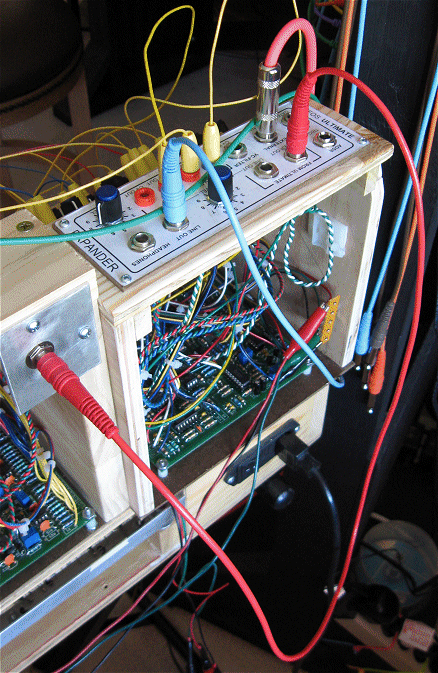
| ULTIMATE connected to the ULTIMATE EXPANDER
Finally here is a shot of the ULTIMATE's MIX OUT connected to the EXPANDER's "FROM ULTIMATE MIXER OUT" jack. The EXPANDER buffers the ULTIMATE's MIX OUT and provides two banana jacks on it's main panel for patching the ULTIMATE's MIX OUT signal into the EXPANDER's modules.
|
|
 |
|
|
|
|
Sound Lab ULTIMATE Patch Points |
|
| Perhaps you have built the ULTIMATE and would like to know how you can add more flexibilty or build another one with additional patch points. This article will show you how. Many of the ULTIMATE's modules are already isolated and adding extra inputs or outputs is fairly obvious. Always isolate patched outputs with 3K resistors so they don't cause problems when plugged in somewhere that doesn't make sense (output to output). When adding additional mixer input resistors whether they be CV or signal mix points always keep the path as short as possible to the mix point. Adding a small daughter board to support the additional components as close to the mix point as you can is always a good idea. Hot glue or double stick tape can be used to secure small daughter boards. | |
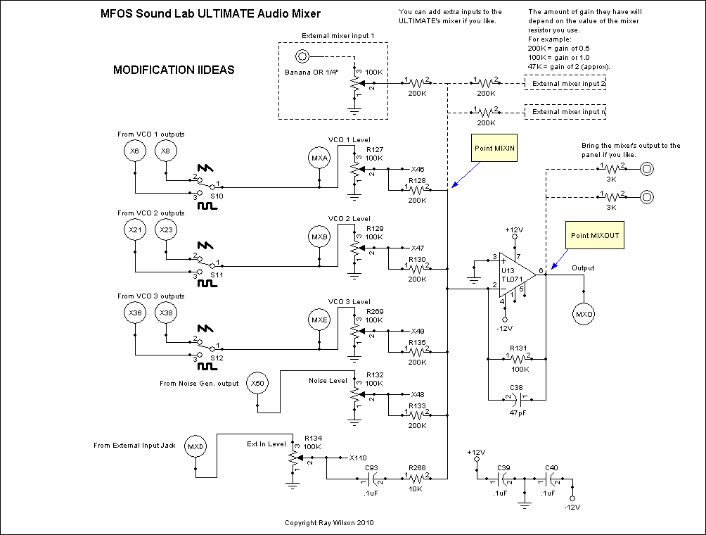
| Modifying/Patching Out the ULTIMATE MIXER
This is all there is to adding inputs to the ULTIMATE's mixer and/or adding mixer out point(s) to the panel. The schematic and corresponding PCB circuit points are shown below.
|
|
 |
|
|
Mod Notes
Keep the lead from the inverting input to the added input mixer resistors as short as possible. Add a small daughter board (Vero or equivalent) near the mixer to support the added resistors. |
|
 |
|
|
|
|
| Isolating/Patching Out the ULTIMATE VCF
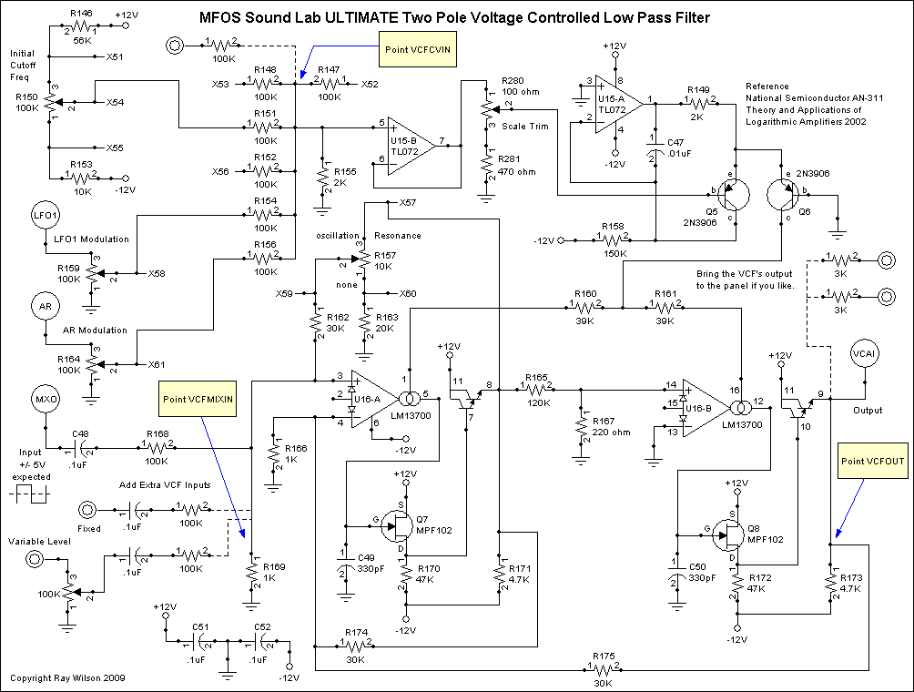
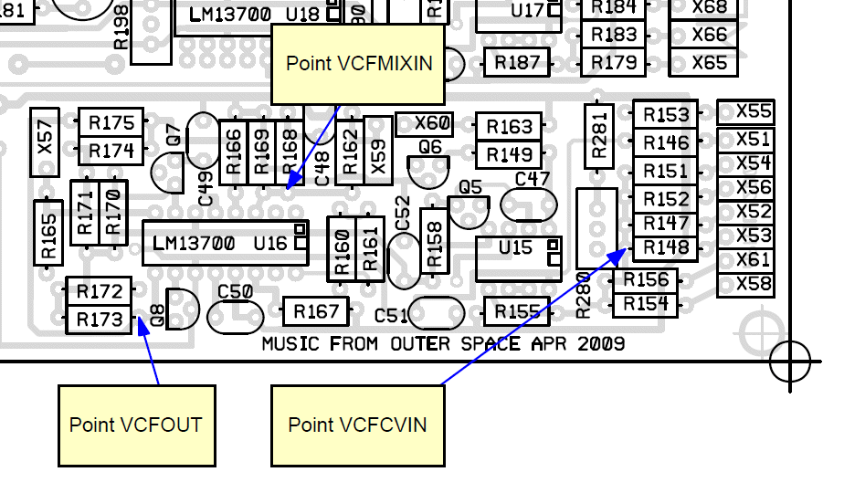
This is all there is to adding extra inputs to the ULTIMATE's VCF, adding extra CV inputs to the VCF and/or adding VCF out point(s) to the panel. The schematic and corresponding PCB circuit points are shown below.
|
|
 |
|
|
Mod Notes
Always keep the path as short as possible to the mix point whether it is an audio or CV mix point. The other side of the mixer resistors can have a lead appropriate in length to get to the panel. Add a small daughter board (Vero or equivalent) near the mix point to support the added resistors. |
|
 |
|
|
|
|
| Isolating/Patching Out the ULTIMATE VCA
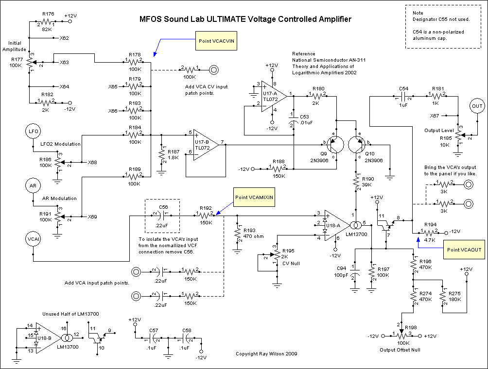
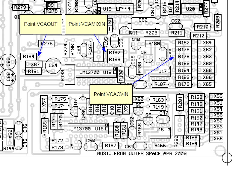
This is all there is to adding extra inputs to the ULTIMATE's VCA, adding extra CV inputs to the VCA and/or adding VCA out point(s) to the panel. The schematic and corresponding PCB circuit points are shown below. As explained in the schematic below isolating the VCA input from the normallized path from the output of the VCF is accomplished by removing C56.
|
|
 |
|
|
Mod Notes
Always keep the path as short as possible to the mix point whether it is an audio or CV mix point. The other side of the mixer resistors can have a lead appropriate in length to get to the panel. Add a small daughter board (Vero or equivalent) near the mix point to support the added resistors and capacitors. |
|
 |
|
|
|
|