Sample & Hold and White Noise Generator
Here is the schematic, PC board layout, and parts placement. Always breadboard first! Have fun.
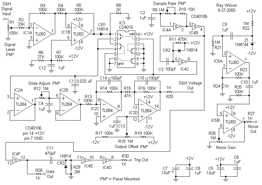
Sample & Hold and White Noise Generator Circuit Schematic

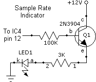
Sample Rate Indicator Mod (not on PCB)

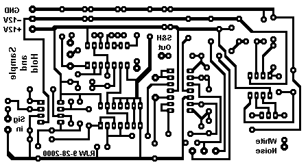
Sample & Hold and White Noise Generator PCB Layout (Component Side View)

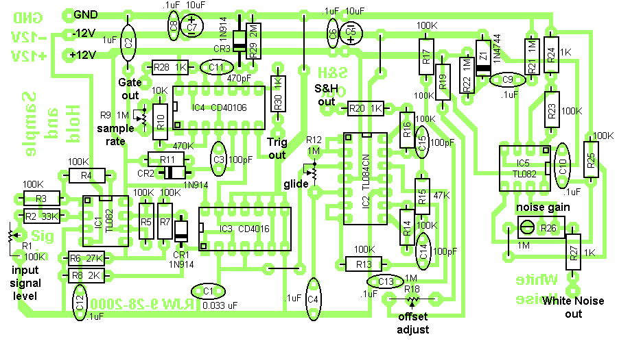
Sample & Hold and White Noise Generator Parts Layout

Sample & Hold and White Noise Generator Parts List
(Thanks to Colin Raffel)
| Qty | Description | Value | Name |
| 1 | Linear Pot | 100k | R1 |
| 1 | Resistor, 1/4 Watt | 33k | R2 |
| 11 | Resistor, 1/4 Watt | 100k | R3, R4, R5, R7, R13, R14, R16, R17, R19, R23, R25 |
| 1 | Resistor, 1/4 Watt | 27k | R6 |
| 1 | Resistor, 1/4 Watt | 2k | R8 |
| 2 | Linear Pot | 1M | R9, R12 |
| 1 | Resistor, 1/4 Watt | 10k | R10 |
| 1 | Resistor, 1/4 Watt | 470k | R11 |
| 1 | Resistor, 1/4 Watt | 47k | R15 |
| 2 | Trimpot, Vert adj | 1M | R18, R26 |
| 5 | Resistor, 1/4 Watt | 1k | R20, R24, R27, R28, R30 |
| 2 | Resistor, 1/4 Watt | 1M | R21, R22 |
| 1 | Resistor, 1/4 Watt | 2M | R29 |
| 1 | Nonpolarized Cap | .033uF | C1 |
| 1 | Nonpolarized Cap | 1uF | C2 |
| 3 | Nonpolarized Cap | 100pF | C3, C14, C15 |
| 8 | Nonpolarized Cap | .1uF | C4, C6, C8, C9, C10, C11, C12, C13 |
| 2 | Polarized Cap | 10uF | C5, C7 |
| 1 | Nonpolarized Cap | 470pF | C11 |
| 3 | High Speed Diode | 1n914 | CR1, CR2, CR3 |
| 1 | Zener Diode | 1n4744 | Z1 |
| 2 | Dual Op Amp | TL082 | IC1, IC5 |
| 1 | Quad Op Amp | TL084 | IC2 |
| 1 | Quad Switch | CD4016 | IC3 |
| 1 | Quad Schmitt Trig | CD40106 | IC4 |