Ray Wilson authored this content while he was actively running MFOS as the founder and resident genius.
We retain the content because it reflects a valuable point of view representing that time and place.
Article by Ray Wilson
| PC Board and Panel Plate Sizes | ||
|---|---|---|
| Item | Size inches | Size mm |
| PC Board | 7.1 x 5.7 | 180.34 x 144.78 |
| Main Panel Plate | 7.0 x 8.75 | 177.8 x 222.25 |
| Aux Panel Plate | 2.5 x 7.0 | 63.5 x 177.8 |
|
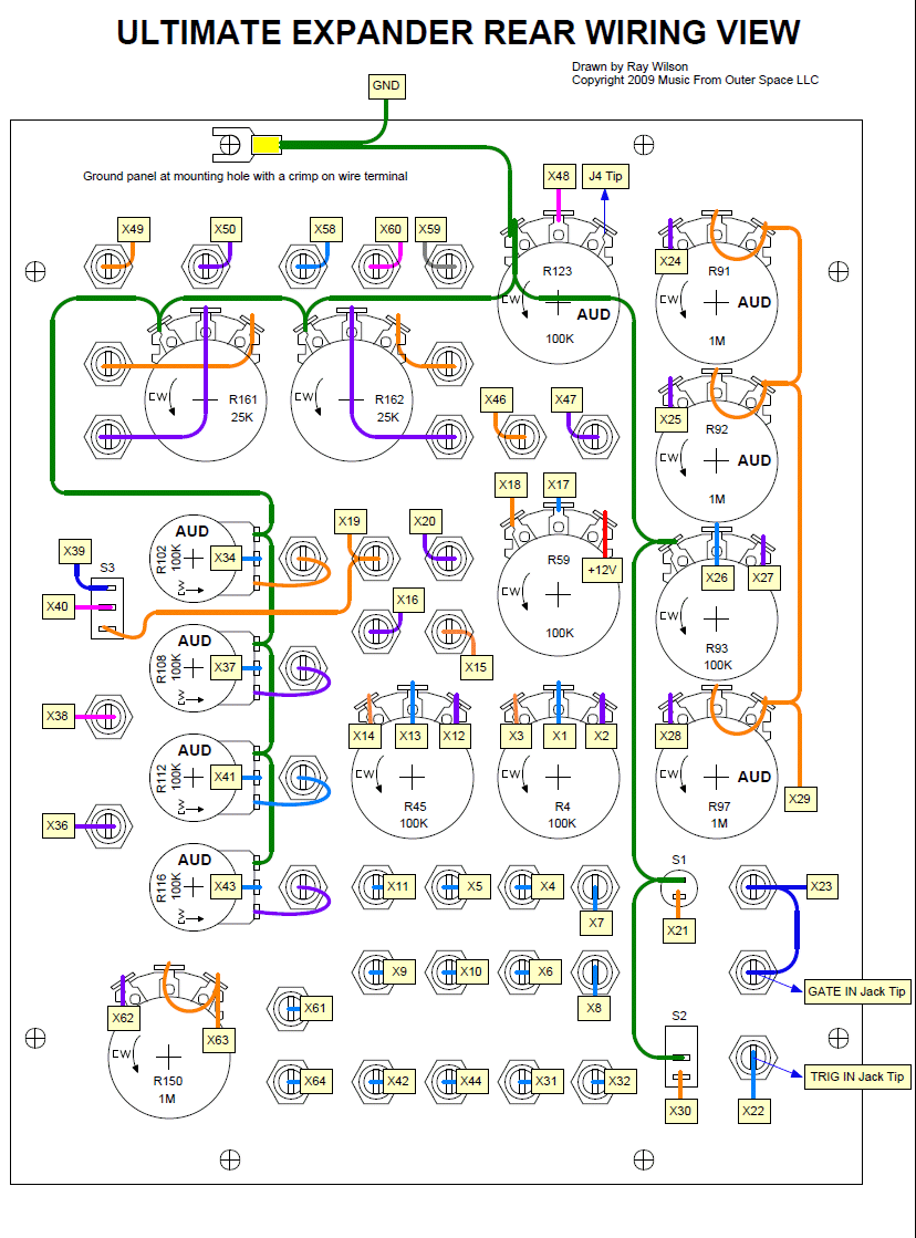
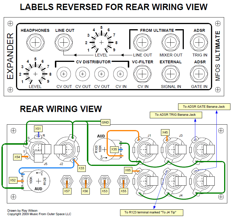
The following assumes that you have completed installing and soldering all of the components onto the PC board. Use a light gauge stranded wire (24 or 26 gauge) for all panel wiring (this is for size and flexibility heavier gauge wire works fine too). To begin the panel wiring phase you should complete the intra-panel wiring, i.e. wire the pots, jacks and switches that are mounted on the panel to one another first. I can say from experience that 99.9% percent of circuit problems are a result of incorrect panel wiring. I can't emphasize how important it is to get the panel wiring right. Follow the steps below to insure that your panel is wired correctly. The procedure may seem tedious but this method is far less tedious than trying to find the problem after everything is wired together and in the case.
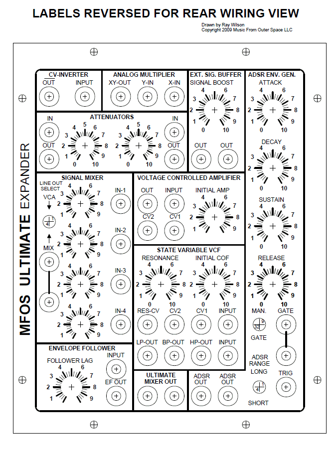
Before beginning to wire the board to the panel you should already have built your case and know the orientation that the board will have in relation to the panel. This will also let you determine how long the wires will need to be (with sufficient slack) to reach from the panel to the case mounted board. Wire the points on this diagram to the corresponding points on the PC Board. I used several colors of wire and used a separate color for each circuit section. Doing so makes each section's wiring easy to identify. As I completed the wiring for a section I wire tied the wires for that section together loosely to make the remaining wiring easier. Don't go nuts with the wire ties just yet because you may need to trace individual wires if you need to trouble shoot later. The more time you take to do a neat wiring job the easier it will be later when you need to test, calibrate and possibly troubleshoot the circuitry. Pot values with an 'AUD' are audio taper. All others are linear taper. The panel is designed with banana jacks in mind. I used two colors, one for inputs and one for outputs. The knobs (or knob skirts) for your pots should not be much over 1/2" in diameter or they will obscure the front panel pot legends. It is important to ground the front panel so that the pot bodies are grounded to reduce EMI noise. This can be accomplished by using a crimp-on wire terminal (Radio Shack as well as most auto parts stores sell these) that you use at one of the front plate mounting hole sites. The crimped on connector is secured between the case and the front panel by the front plate mounting screw and in this manner makes a solid contact with it. Run the crimped-on wire that is in contact with the front plate to the power supply ground.
|


