Ray Wilson authored this content while he was actively running MFOS as the founder and resident genius.
We retain the content because it reflects a valuable point of view representing that time and place.
Article by Ray Wilson
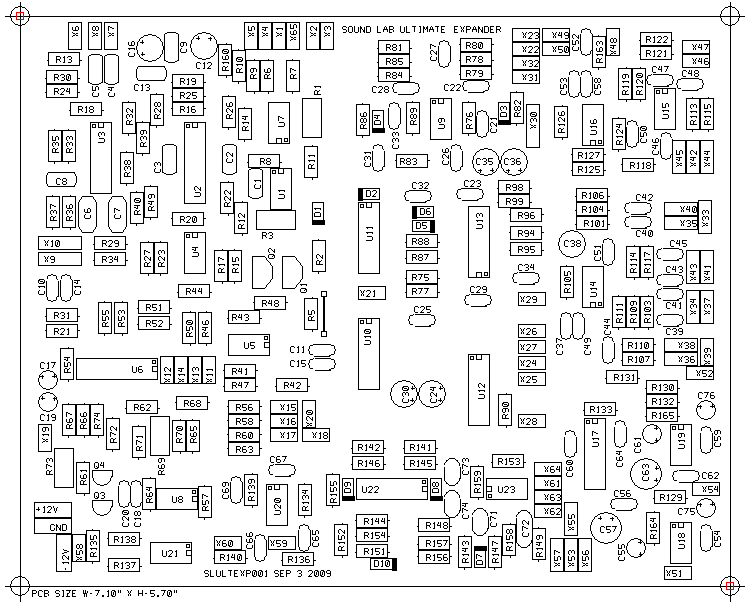
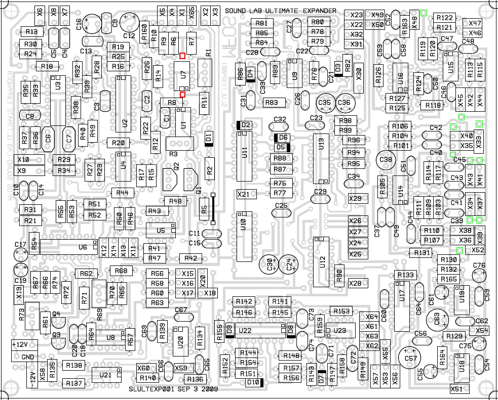
The green markers on the ULTIMATE EXPANDER PCB Parts Layout are indicators of ground terminal access for connecting the shield of the coax or the ground wire of a twisted pair to reduce reflection of signals from wire to wire.
The red markers on the ULTIMATE EXPANDER PCB Parts Layout are indicators of the pads that can be used to mount a metal film 2K Ohm 1/4W +/-2% T.C. +3300 PPM tempco in contact with the filter's matched transistor pair. If you use those pads with a tempco DO NOT INSTALL R11. The tempco functions as R11. Using a tempco will reduce the filter's temperature related drift.
There is one wire jumper on the PC board for which you must insert a piece of wire. It can be stranded or solid wire and the gauge does not matter as long as it fits in the holes. It is located a bit left of the center of the board, next to designator R5. It is the legend that looks like a short black line with a square on each end. The squares mark the two pads that the jumper connects.
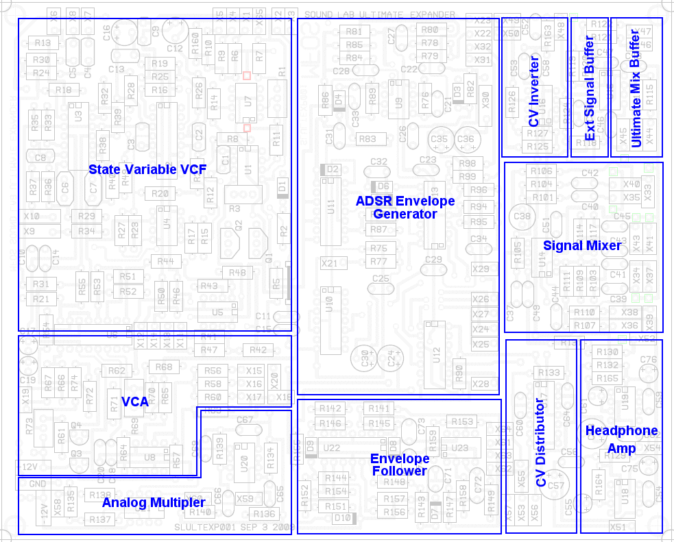
ULTIMATE EXPANDER Module Map
This view shows the locations of the various modules on the PC board. While doing some troubleshooting recently I found out first hand that this is a handy thing to have.
ULTIMATE EXPANDER PCB Parts Layout (Parts Side Shown) PDF
This view is very useful for trouble shooting where you need to reference the designators.
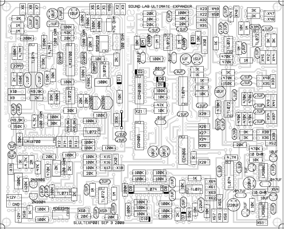
ULTIMATE EXPANDER PCB Parts Values (Parts Side Shown) PDF
This view is very useful when populating the board where you need to stuff it with the correct values. It saves you from having to constantly refer to the parts list.
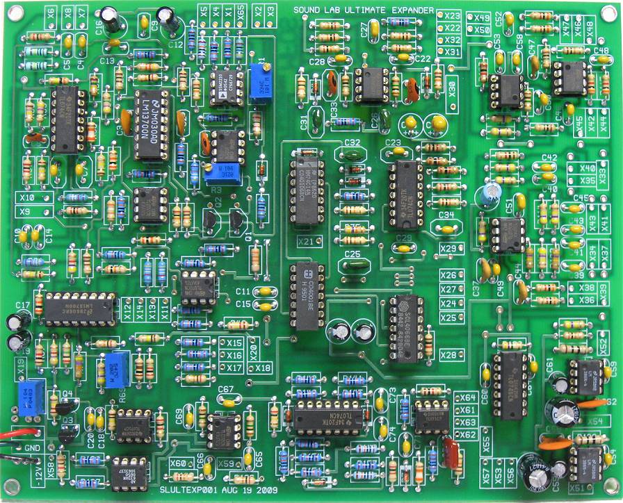
ULTIMATE EXPANDER Populated PCB
This is the prototype board with all components soldered in place and the chips installed into their sockets. I used this board to build the test unit. Since I used a prototype board I soldered the suggested kludges to the bottom of the board so it works just like a production PCB does. The production boards are revised so that they do not need any kludges. You only need the kludges if you bought a prototype PC board. Notice that I ALWAYS use good IC sockets. Use at the least, gold plated contact machined sockets. There are of course some minor differences in the production boards but this gives you an idea of the sizes of components I used. You can also see the top side fillets which indicate that the solder joints are well soldered. Use them as an indicator to help you find unsoldered leads or joints that need attention.
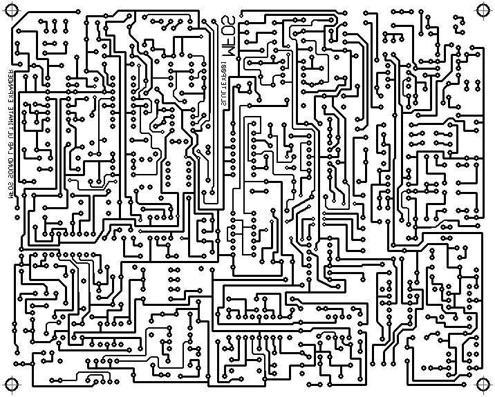
ULTIMATE EXPANDER PCB Bottom Copper For Reference (Top Side View Shown)
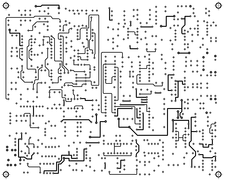
ULTIMATE EXPANDER PCB Top Copper For Reference (Top Side View Shown)
ULTIMATE EXPANDER PCB Top Silk Screen For Reference
