Ray Wilson authored this content while he was actively running MFOS as the founder and resident genius.
We retain the content because it reflects a valuable point of view representing that time and place.
Article by Ray Wilson
 |
Getting Everything Working(Do a browser control-refresh to insure you have the latest info.) |
If your WSG has extremely low level output the output jack is probably wired backwards. Look it over carefully and make sure that the WSG PCB's circuit point (OUT) connects to the jack's "tip" connector and that the WSG PCB's circuit point (GND) connects to the jack's ring (ground) connection. This is an especially common problem when the output jack used has more than two terminals as they are not always arranged in the same way.
- Print out a copy of the "MFOS Weird Sound Generator PCB Parts Layout (Values Shown)" and go over your circuit board to make sure every part is present and accounted for. Mark it on
the drawing as you verify it's presence and correct value. MAKE SURE THE BATTERY WIRES ARE CONNECTED CORRECTLY.
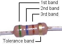
Check all of the resistors to make sure they are the correct values (color codes go from left to right and start on the side of the resistor opposite the tolerance band (gold band)):
Reading Resistor ValuesValue 1st band 2nd band 3rd band 1K brown black red 4.7K yellow violet red 47K yellow violet orange 100K brown black yellow 470K yellow violet yellow 750K violet green yellow 1M brown black green 10M brown black blue 
The capacitors must also all have the correct values. Check them out too.
Here is some help reading capacitor values.The electrolytic caps (small can looking things with two leads) must be installed with correct orientation. They are marked to show the correct orientation with either a plus sign, in which case you insert it so that it's plus symbol is aligned with the PCB legend's plus symbols, or with a negative symbol in which case you insert it so that it's negative symbol is opposite the PCB legend's plus symbols. Electrolytic caps don't take kindly to being installed backward but will probably be OKAY once you reinstall any correctly.
Make sure the IC chips are installed so that the marking on the chip indicating pin one is oriented correctly. The legend on the board for the chips has a marking for where pin one goes. Make sure the sockets are oriented correctly. There is a "pin 1 end" marking that must align with the PC board's screened "pin 1 end" legend. If the socket is backwards it is perfectly OK to reverse the chip in the socket to correct the situation.
If you had a chip backwards you will probably need to buy a new one because that chip has probably died. Chips HATE being powered backwards. It's like murdering an innocent chip when you do that (shame on you).
- Print out a copy of the panel wiring drawing and look over your wiring and highlight each wire one at a time on the drawing as you verify that it is installed and soldered properly.
This is a VERY LIKELY place where you will find an error.
Now you need a signal tracer or an oscilloscope. As the info on using your amp as a signal tracer says... TURN IT WAY DOWN NOW (like between 0 and 1). The levels of the signals we will be probing are VERY HIGH compared to a guitar and you can BLOW YOUR SPEAKERS. So again... TURN IT WAY DOWN NOW (like between 0 and 1).
Trouble Shooting By Following The Schematic:
In the following test steps I often say to "look at" (probe with an oscilloscope) or "listen to" (probe with a signal tracer) a particular circuit point identified by an IC pin or component designator. In order to track down a problem it is also necessary to probe any point that the schematic shows is connected to the point I mention. This technique will become second nature to you once you get a bit of trouble shooting experience under your belt. Only by doing so will you discover any mis-wiring that may be present in your WSG so you can correct it (and get on with the business of making weird sounds).
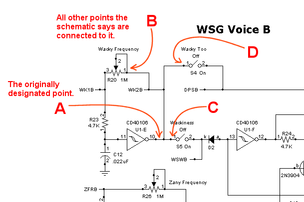
For example: Performing this step which is taken from the section Testing Wacky Function (Voice B).
- Look at on the scope or listen to point: U1-E pin 10. Adjust Wacky Frequency pot R20 until it is oscillating slowly (a few hertz per second).
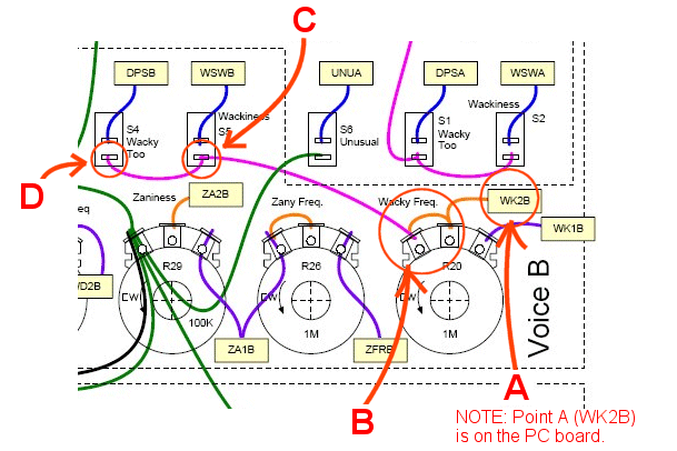
would involve looking at all these circuit points.
As you can see the designated point is connected to several other points in the schematic. It is very important to check all of the points connected to the designtated point. If you find that the signal is not present at one of these connected places... VOILA! you just discovered a wiring error. 
Following the schematic involves identifying the points on both the PC board and the front panel where the schematic says a connection should exist and then probing it to see if the signal is there. The designators on the PC board (WK2B for example) must have a wire running from the PC board to the corresponding point shown in the panel wiring diagram. Notice too that if a point terminates at a switch that when the switch is on the signal should be present on both sides of the switch and everything the schematic says it connects to as well. If a point terminates at a pot then when the pot is adjusted the signal (perhaps attenuated) should be present on at least one of the other pot terminals (one terminal may be grounded and thus you shouldn't see the signal there, unless you didn't ground the terminal that should be grounded... see how this works). And again when you see a signal on a pot the signal should be present wherever the schematic says that pot terminal is connected to.

Trouble shooting is a necessary skill that you need to cultivate if you intend to pursue the hobby of electronics. The WSG is a very simple circuit and a good learning tool. By applying the technique I just discussed to the following steps you will find any bugs with your WSG. With patience and persistence you will succeed. Good building!Testing Each Oscillator:
Before you begin these steps
- TURN S2 (Voice-A-Wackiness) and S5 (Voice-B-Wackiness) OFF
- Turn Zaniness Amount pots R18 and R29 all the way DOWN (counter clockwise).
- Look at on the scope or listen to point: U1-B pin 4. You should hear a square wave signal that varies in frequency with adjustment of Wacky Frequency pot R1.
- Look at on the scope or listen to point: U1-A pin 2. You should hear a square wave signal that varies in frequency with adjustment of Weird Frequency pot R9.
- Look at on the scope or listen to point: U1-C pin 6. You should hear a square wave signal that varies in frequency with adjustment of Zany Frequency pot R13.
- Look at on the scope or listen to point: U1-E pin 10. You should hear a square wave signal that varies in frequency with adjustment of Wacky Frequency pot R20.
- Look at on the scope or listen to point: U1-F pin 12. You should hear a square wave signal that varies in frequency with adjustment of Weird Frequency pot R25.
- Look at on the scope or listen to point: U1-D pin 8. You should hear a square wave signal that varies in frequency with adjustment of Zany Frequency pot R26.
If one of the oscillators is not functional then you may have an associated component (a component connected to it as shown in the schematic) that is not properly installed in the circuit board. Or the wires connecting the frequency adjustment pot for that oscillator may be mis-wired. Last but not least is is possible to statically damage one of the gates in a CD40106 chip and you may need to purchase a new one.
Testing Wacky Function
Before you begin these steps
- TURN S2 (Voice-A-Wackiness) ON
- TURN S5 (Voice-B-Wackiness) ON
- Turn Zaniness Amount pots R18 and R29 all the way DOWN (counter clockwise).
Voice One
- Look at on the scope or listen to point: U1-B pin 4. Adjust Wacky Frequency pot R1 until you see and/or hear it oscillating slowly (a few hertz per second).
- Look at on the scope or listen to point: U1-A pin 2. Adjust Weird Frequency pot R9 to about mid range (half way up).
- The signal at U1-A pin 2 should be going on an off at the rate of the Voice 'A' Wacky oscillator.
- Turning S2 (Voice-A-Wackiness) off should stop the on-off effect and you should see and/or hear the Weird oscillator oscillating normally.
- Turning S2 (Voice-A-Wackiness) on again and changing the rate of the Wacky oscillator should affect how often the weird oscillator for Voice 'A' turns on and off.
- Turning Wacky Frequency pot R1 up higher should start to make the Voice 'A' Weird oscillator sound EVEN WEIRDER.
Voice Two
- Look at on the scope or listen to point: U1-E pin 10. Adjust Wacky Frequency pot R20 until you see and/or hear it oscillating slowly (a few hertz per second).
- Look at on the scope or listen to point: U1-F pin 12. Adjust Weird Frequency pot R25 to about mid range (half way up).
- The signal at U1-F pin 12 should be going on an off at the rate of the Voice 'B' Wacky oscillator.
- Turning S5 (Voice-B-Wackiness) off should stop the on-off effect and you should see and/or hear the Weird oscillator oscillating normally.
- Turning S5 (Voice-B-Wackiness) on again and changing the rate of the Wacky oscillator should affect how often the weird oscillator for Voice 'B' turns on and off.
- Turning Wacky Frequency pot R20 up higher should start to make the Voice 'B' Weird oscillator sound EVEN WEIRDER.
Again if something is not going according to plan then you may have an associated component that is not properly installed in the circuit board. Or the wires connecting R1, S2 (Voice-A-Wackiness), R20 or S5 (Voice-B-Wackiness) to the PC board may be mis-wired.
Testing Zany Function
Before you begin these steps
- TURN S2 (Voice-A-Wackiness), S5 (Voice-B-Wackiness), S6 (Voice-A Unusual), and S7 (Voice-B Unusual) all OFF
- Turn Zaniness Amount pots R18 and R29 all the way DOWN (counter clockwise).
Voice One
- Look at on the scope or listen to point: U1-C pin 6. Adjust Zany Frequency pot R13 until you see and/or hear it oscillating slowly (a few hertz per second).
- Look at on the scope or listen to point: U1-A pin 2. Adjust Weird Frequency pot R9 to about mid range (half way up).
- As you turn R18 up (clockwise) slowly, the signal at U1-A pin 2 should begin to be modulated (step up and down in pitch).
- Turning S6 (Voice-A Unusual) on should cause the modulation to sweep up and down in pitch instead of step as before.
- Advancing R13 should speed up the modulation frequency.
- R13 should allow you to adjust the modulation rate and R18 the modulation depth. R9 will change the range of the modulation up or down.
Voice Two
- Look at on the scope or listen to point: U1-D pin 8. Adjust Zany Frequency pot R26 until you see and/or hear it oscillating slowly (a few hertz per second).
- Look at on the scope or listen to point: U1-F pin 12. Adjust Weird Frequency pot R25 to about mid range (half way up).
- As you turn R29 up (clockwise) slowly, the signal at U1-F pin 12 should begin to be modulated (step up and down in pitch).
- Turning S7 (Voice-B Unusual) on should cause the modulation to sweep up and down in pitch instead of step as before.
- Advancing R26 should speed up the modulation frequency.
- R26 should allow you to adjust the modulation rate and R29 the modulation depth. R25 will change the range of the modulation up or down.
Again if something is not going according to plan then you may have an associated component that is not properly installed in the circuit board. Or the wires connecting R13, R18, S6 (Voice-A Unusual), R9 or R26, R29, S7 (Voice-B Unusual), R25 to the PC board may be mis-wired.
Testing Oddness Filter Function
Before you begin these steps
- TURN S1 (Voice-A Wacky Too) and S4 (Voice-B Wacky Too) ON
- TURN S2 (Voice-A-Wackiness) and S5 (Voice-B-Wackiness) OFF
- ADJUST R1, R9, R20, and R25 to about mid range (half way up).
- Turn Zaniness Amount pots R18 and R29 all the way DOWN (counter clockwise).
- Look at on the scope or listen to both sides of R2.
- When probing one side you will hear (or see) the output of U1-B pin 4 very strongly and on the other side all four oscillators mixed together and at a MUCH LOWER LEVEL.
- Adjust R1 Wacky Frequency while you probe the side with the strong signal. The strong signal should go up and down in pitch.
- Adjust R1 Wacky Frequency while you probe the side with the soft/low level signal. You should hear (or see) the frequency going up and down in among the 4 oscillator mix at a MUCH LOWER LEVEL.
- Look at on the scope or listen to both sides of R5.
- When probing one side you will hear (or see) the output of U1-A pin 2 very strongly and on the other side all four oscillators mixed together and at a MUCH LOWER LEVEL.
- Adjust R9 Weird Frequency while you probe the side with the strong signal. The strong signal should go up and down in pitch.
- Adjust R9 Weird Frequency while you probe the side with the soft/low level signal. You should hear (or see) the frequency going up and down in among the 4 oscillator mix at a MUCH LOWER LEVEL.
- Look at on the scope or listen to both sides of R21.
- When probing one side you will hear (or see) the output of U1-E pin 10 very strongly and on the other side all four oscillators mixed together and at a MUCH LOWER LEVEL.
- Adjust R20 Wacky Frequency while you probe the side with the strong signal. The strong signal should go up and down in pitch.
- Adjust R20 Wacky Frequency while you probe the side with the soft/low level signal. You should hear (or see) the frequency going up and down in among the 4 oscillator mix at a MUCH LOWER LEVEL.
- Look at on the scope or listen to both sides of R22.
- When probing one side you will hear (or see) the output of U1-F pin 12 very strongly and on the other side all four oscillators mixed together and at a MUCH LOWER LEVEL.
- Adjust R25 Weird Frequency while you probe the side with the strong signal. The strong signal should go up and down in pitch.
- Adjust R25 Weird Frequency while you probe the side with the soft/low level signal. You should hear (or see) the frequency going up and down in among the 4 oscillator mix at a MUCH LOWER LEVEL.
And once again if something is not going according to plan then you may have an associated component that is not properly installed in the circuit board. Or some mis-wiring.
Before you begin these steps
- Turn Coarse Cut Off R3 all the way up, Fine Cut Off R31 about mid level, and Oddness Resonance R32 to mid level.
- TURN S1 (Voice-A Wacky Too) and S4 (Voice-B Wacky Too) ON
- TURN S2 (Voice-A-Wackiness) and S5 (Voice-B-Wackiness) OFF
- ADJUST R1, R9, R20, and R25 to about mid range (half way up).
- Turn Zaniness Amount pots R18 and R29 all the way DOWN (counter clockwise).
- Look at on the scope or listen to point: U2 pin 6.
- Adjusting R31 up or down should affect the amount of high frequency content in the signal.
- Adjusting R3 up or down should affect the amount of high frequency content in the signal (more coarsely).
- Adjusting R32 up or down should affect the amount of resonance (ringiness) in the signal.
- Look at on the scope or listen to point: OUT (pin of C6).
- Adjusting R31 up or down should affect the amount of high frequency content in the signal.
- Adjusting R3 up or down should affect the amount of high frequency content in the signal (more coarsely).
- Adjusting R32 up or down should affect the amount of resonance (ringiness) in the signal.
Repeating again... if something is not going according to plan then you may have an associated component that is not properly installed in the circuit board. The LM741 is a pretty forgiving part but installing it backwards or connecting the battery backwards may severely damage it. Replace it with a known good one if you suspect it. Mis-wiring can again be the culprit as well.
I and many others can attest to the fact that putting the circuit together properly will result in sounds like those of the samples above. I hope this info helps you get your WSG going. There is really nothing I can say beyond what I have suggested here. If you need more help I suggest that you consult an electronics savvy friend who can help you in person and actually see the wires and probe the circuit.
Cheers and best of luck, Ray