|
||||||||||||||||
| The MFOS SCOOP | In This Issue | MFOS Has Parts For Sale | ||||||||||||||
|
Hi Everyone!
The MFOS SCOOP is being sent at your request to keep you in the loop regarding MFOS. I'll try to get something out every month or two. MFOS' mission is to be the most informative synth-DIY site on the planet. We're here to help you keep imagining, keep inventing, and stay ingenious! If you have any suggestions about what you would like to see in an issue of The MFOS SCOOP email me. Please forward this to any of your friends who have an interest in synth-diy.
|
This issue of The MFOS SCOOP has some great information.
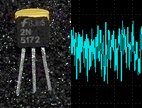
New! Selected 2N5172 noise transistor.
Noise level greater than 3V pp with non-inverting gain of 100.
|
Finding all of the parts MFOS has for sale is easy on
the new MFOS website.
Just click the search icon (magnifying glass) and enter parts
into the Search for keyword(s) text box, click the search button
and up comes the current list of available parts.
AD633AN Analog Multiplier
NEW! Metal film tempcos are on the way! Stay tuned for more excellent parts for your projects. |
||||||||||||||
|
||||||||||||||||
|
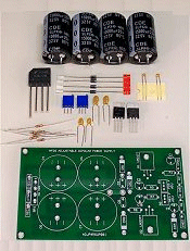
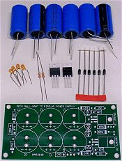
Now building a power supply is easier than ever. MFOS is now offering two
power supply parts kits. YOU MUST SUPPLY YOUR OWN WALL WART OR TRANSFORMER.
The kits contain all of the parts for your synth's power supply except for the wall wart and/or transformer. The LM317/LM337 kit can power an entire case of modules with it's adjustable voltage and 1.5A maximum capability. The wall wart kit can hold its own as well and can easily power an ULTIMATE and ULTIMATE EXPANDER or a Sound Lab Mini-Synth no problem.
|
||||||||||||||||
|
||||||||||||||||
|
||||||||||||||||
|
||||||||||||||||
|
||||||||||||||||
|
||||||||||||||||
|
Op amps are one of the most versatile components you can work with as a synth-diy or electronics enthusiast.
They are in just about every synth-diy circuit out there as well as in just about anything dealing with audio.
There are many many types of op amps and many of them come close to the ideal op amp. What is the ideal
op amp. Well it would have infinite input impedance, absolutely zero DC input current, absolutely zero offset voltage,
an infinite gain bandwidth product and lastly absolutely zero output impedance. I'd also like to add that if it ran on
sunshine and lemonade then that would be a plus. We're going to cover a couple of subjects related to op amps. How to power an
op amp from a single 9V battery and a bit of op amp theory.
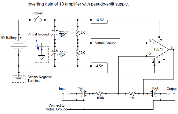
Powering An Op Amp From One 9V BatteryOp amps require a split or bipolar supply for normal operation. That means that you can't just apply 9V and ground to an op amp circuit and start using it. You need to have a positive side, a negative side and a ground. Well how can we get a positive, negative and ground from just one 9V battery. The image below shows an inverting gain of ten buffer that uses one 9V battery for power.
This circuit makes use of what is known as a virtual ground. The virtual ground is a voltage level that is 1/2 the supply voltage (the supply voltage is 9V in this case). The junction of the two resistors and two capacitors becomes the actual virtual ground point in the circuit. When you measure between the virtual ground (using your meter's black lead) and the + side of the battery (using your meter's red lead) you see +4.5V. When you measure between the virtual ground (using your meter's black lead) and the - side of the battery (using your meter's red lead) you see -4.5V. This is just what we need to power an op amp (or several op amps). Notice that we use the virtual ground for the sleeve connections of the jacks as well. We isolate the input and output from the outside world capacitively. We use a 1uF on the input and a 10uF on the output. This circuit faithfully reproduces whatever signal you inject times 10. If you inject too hot of a signal the op amp will clip at about 3.5V to 4V. Just keep in mind that the virtual ground is where all circuitry gets its ground reference in the circuit.
Some Op Amp Insight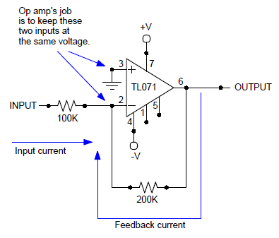 We get used to using op amps and we know that if we change the ratio of the input resistor to the feedback resistor the gain changes.
But why? We also know that when we use an op amp in a comparator application that the output shoots to the maximum voltage possible
for the op amp when one input is brought above or below the other. But why? Well lets take a look and see if by increasing our understanding
of how the op amp does what it does we are better able to use them in the future.
In essence when we use an op amp in the inverting configuration as shown in the illustration the op amp's main job is to try and keep the inverting input at the same voltage as the non-inverting input. So when we connect the non-inverting input to ground the op amp tries to keep the inverting input at the same voltage level. This phenomenon is the same reason that the inverting input configuration makes such a great signal mixer. The inverting input is referred to as a virtual ground (not the same as the discussion above) but it is a reference to the fact that when the non-inverting input is grounded and we use negative feedback the inverting input is held at ground by the action of the op amp's internal circuitry and the feedback resistor. Consider the circuit in the illustration. If we apply +1V to the input and remembering that the op amp is trying to keep the inverting input at ground we know that there are 10 uA flowing though the 100K input resistor to the inverting input. What mechanism keeps the inverting input from rising to 1V? The feedback resistor and the op amp's internal circuitry are the culprits. We intuitively know that the output of the op amp will be -2V since we have a 200K feedback resistor and we know the gain formula for the inverting op amp configuration is (feedback resistor value)/(input resistor value). But lets look deeper. When the output of the op amp is -2V we are pulling 10uA in the other direction through the 200K feedback resistor and toward the output. This is what keeps the inverting input voltage from rising to 1V and what causes the output to go to -2V. The output via the feedback resistor pulls away the necessary amount of current to balance what arrives at the inverting input. If we applied 2V to the input we would have 20uA flowing to the inverting input via the 100K resistor. How high would the output voltage have to go now to balance the current arriving at the inverting input? Well we need 20uA to flow away from the inverting input so the output would need to go to -20uA x 200K or -4 volts. By adding frequency selective components to the feedback network we can cause some signals to have more gain and some to have less gain (also known as filtering). Thus if you put a cap in parallel with the feedback resistor you are inviting higher frequency signals a ready path back to the inverting input and thus they op amp applies less gain to them and you end up with a simple low pass filter. With a better understanding of why the op amp applies gain to its output signal in the inverting configuration you can better understand how filtering networks do their thing. Although we are talking about applying simple DC levels to the input of the op amp remember that this is the same mechanism at work in AC op amp applications as well.
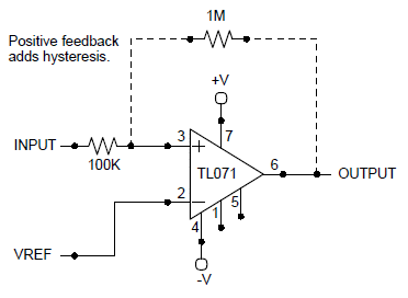
Well what if we don't have a feedback resistor? When we use an op amp without a feedback resistor it is generally because we desire the op amp to act as a comparator. Now lets say we apply +1V to the non-inverting input of the op amp and ground to the inverting input (we call this VREF) what happens? The op amp detects that we have an imbalance on the inputs and attempts to correct it. The non-inverting input voltage is higher than the inverting input voltage so the output of the op amp goes as high as it can (usually 1 to 1.5 volts from the supply voltage). If there was a feedback resistor the output would be trying to balance the inputs and pull the inverting input up to the level of the non-inverting input. But since there is none and no one bothered to tell the op amp it tries in vain to balance the input voltages by pushing the output as high as it can go. Now if the non-inverting input sees -1V the output will go as low as possible again in vain since there is no feedback resistor to help balance the inputs. Now you know why the comparator does what it does. What's positive feedback? It's when you feed a portion of the output signal back to the non-inverting input. You see this in filters from time to time to help give the filter the desired response (filters are a whole other advanced topic). You also see it in comparators. In a comparator the effect of positive feedback is to add what is known as hysteresis to the response of the comparator. With no hysteresis a comparator can be a very finicky beast near it's threshold (VREF). Any noise on the supply can find it's way to the comparator's reference (VREF) so that it may chatter (oscillate high and low) when about to change states instead of smoothly jumping to either the high or low state. Let's say we are making a comparator and we want to apply the reference (VREF) to the inverting input and the signal that causes the comparator to go high or low to the non-inverting input (as shown in the illustration). This is a non-inverting comparator. When the input is above the reference (VREF) the output goes high and when it is below the reference the output goes low. If we now add a positive feedback resistor from the output of the op amp back to the non-inverting input we cause the comparator to have hysteresis. It is important to understand that in order for everything to work properly you need to insert a resistor between the signal you are detecting (the level that causes the comparator to change states) and the non-inverting input. Also the ratio of the input resistor to the positive feedback resistor is what sets the amount of hysteresis. The lower the value of the positive feedback resistor the greater the amount of hysteresis. If the feedback resistor if too low in value the comparator may never change states. In general a feedback resistor of 10 to 20 times the input resistor results in an acceptable level of hysteresis for general comparator applications. There are, of course, times when you want more or less than that. Here is what happens with a positive feedback resistor. Lets say the non-inverting input is higher than the inverting input (VREF) and the op amp's output is high. Now the output is holding the non-inverting input high through the feedback resistor. The signal fed into the non-inverting input via the 100K resistor now has to go low enough to pull the non-inverting input below VREF despite the help that the non-inverting input is getting to stay high from the op amp's output via the positive feedback resistor. Once the signal goes low enough the output shoots low. In this case the output is helping to speed up the transition to the low state because it is tied to the non-inverting input remember. And just as you thought now the input has to go high enough to fight the feedback resistor which is holding the non-inverting input low. A trick to use to get the fastest response out of your op amp comparator is to add a small value cap (1pF to 20pF) in parallel with the positive feedback resistor. This causes the edge of the rising or falling output to get fed back to the non-inverting input almost immediately which speeds up the rise or fall time to just about as fast as the op amp will go. I hope these tips help improve you understanding of op amps and comparators. Cheers, Ray |
||||||||||||||||
|
||||||||||||||||
|
||||||||||||||||
|
||||||||||||||||
|
||||||||||||||||


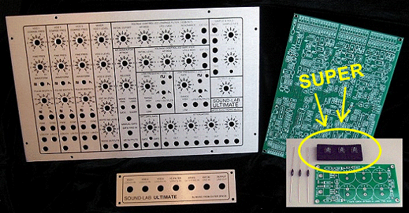
 You'll be glad you looked at this if you are in the market for a Sound Lab ULTIMATE SUPER Deal Clincher Pack!
This newsletter Special of the Month is the Sound Lab ULTIMATE SUPER Deal Clincher Pack but wait there's more... (I've always wanted to say that).
Instead of just getting the PC board for the wall wart you will receive the wall wart parts kit and the price? $160.00.
