Ray Wilson authored this content while he was actively running MFOS as the founder and resident genius.
We retain the content because it reflects a valuable point of view representing that time and place.
Article by Ray Wilson
Features
- Simultaneous Sine, Triangle, Saw, Ramp, and Variable Pulse Width Rectangle Outputs.
- Voltage Control of Frequency (approximate log response, NOT 1V/Octave)
- Voltage Control of Rectangle Pulse Width
- Fine and Coarse Frequency Control
- Very Low Frequency (1 Cycle per several minutes)
- Output levels are all approximately +/-5V (+ or - 300 mV).
Introduction
This is a nice LFO for all of your modulation needs. The frequency can be voltage controlled to add a new dimension to your sound palette. The pulse width of the rectangle wave can be varied between approximately 10% and 90% again lending variability to the modulation capabilities of this LFO. Voltage control can be used to vary the pulse width as well. If you power your circuits with +/-15 volts then observe the recommended changes that are noted on the schematic. I recommend a complete review of this page before buying a board.Voltage Controlled LFO Schematic Page 1 PDF

|
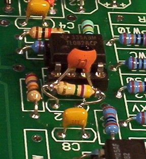
U1 and associated components comprise a linear voltage to log current converter. The current flowing into the collector of Q2 controls the current flowing from the bias input of U3-A transconductance amp to ground via Q3. The transconductance of U3-A is used to control the frequency of the oscillator. U2-A and associated components comprise an integrator. When current flows into U3-A's output the integrator ramps up and when current flows out of U3-A's output the integrator ramps down. When the integrator's output goes above the threshold of comparator U4-A and associated components it's output goes high (to near +V). The output of U4-A is fed to the non-inverting input of U3-A transconductance amp. While U4-A's output is high current flows out of U3-A's output and the integrator ramps down until the voltage at the input of U4-A goes low enough to overcome the hysteresis provided by R18 and it's output goes low. When this happens the comparator starts to ramp up again and thus we have a triangle wave at the output of U2-A. The amp bias of U4-A is controlled by the current generated by the linear voltage to log current convertor. This controls the current that flows in and out of U4-A and thus the frequency of the oscillator. The oscillator's frequency can be varied from super low (a cycle takes over two minutes) to about 600 HZ. Don't hold my feet to the fire on exact range. When I turn it all the way down and listen to it's effect on an oscillator, I can just discern the change in frequency as the voltage ramps up or down. I insured that at the lowest setting the comparator still trips high and low. You could probably increase C11 if you want it to go lower. The frequency goes up with higher control voltage and down with lower control voltage I do not advertise that the oscillator tracks well and will give you 1V per octave. In my applications of low frequency oscillators I do not need this capability. IF YOU NEED 1V/OCT TRACKING, THEN THIS IS NOT THE VC-LFO FOR YOU.. I don't mean to shout with the bold caps, I just don't want people to miss that point. Trim pot R25 is used to balance the current flowing during the high and low periods of U4-A. With the coarse frequency set to about mid-way and while viewing the output of U2-A adjust R25 until the symmetry of the triangle waveform is as perfect as you can get it. You can use the scope's non-calibrated horizontal sweep adjust and horizontal position controls to help get one cycle displayed properly too. The symmetry of the triangle waveform will affect all of the other waveforms and is thus very important to get right. Use the output of U4-A to trigger the scope so that one triangle cycle is displayed on the scope (low to high to low OR high to low to high). The goal is to get the wave to start at the left end of the graticule, peak (or valley) at the exact center of the graticule, and then end at the right end of the graticule. Once the triangle symmetry is adjusted observe the output of U5-A (ramp wave output). The ramp wave is created by mixing portions of the original triangle wave and an inverted version of the triangle wave. N-FETs Q4 and Q5 are used as analog switches. N-FET Q5, which switches the original version of the output of U2-A, is controlled by the inverted output of U4-A (oscillator comparator). N-FET Q4 , which switches the inverted version of the output of U2-A, is controlled by the original output of U4-A (oscillator comparator). When U4-B's output is high (U4-A's output is low) the drain of Q5 follows the output of U2-A (the drain of Q4 floats). When the oscillator comparator (U4-A) reaches it's threshold and U4-A goes high the inverted version of U2-A appears at the drain of Q4 (drain of Q5 floats). The signal at the drain of Q4 is biased up and the signal at the drain of Q5 is biased down so that the rising portion of the signal from the drain of Q5 meets the rising portion of the signal from the drain of Q4 resulting in a continuous ramp wave that goes from the valley of the signal at the drain of Q5 to the peak of the signal at the drain of Q4 and then rapidly back down to the valley of the signal at the drain of Q5. The output of U5-B is an inverted version of the ramp which is typically called a sawtooth. This waveform shoots high and then goes low slowly. Adjust R46 so that the ramp wave is continuous and does not have a positive or negative step at the moment that the FETs switch. To do this I set the coarse frequency to about mid-way and trigger my scope with the falling edge of the ramp wave and then tune the LFO frequency so that one complete cycle is seen on the scope. You can use the scope's non-calibrated horizontal sweep adjust and horizontal position controls to help get one cycle displayed properly too. Adjust the ground level of the scope to the center vertical division of the graticule. Then adjust the gain of the scope higher and higher to emphasize the step. If your scope has a X10 for the horizontal sweep turn it on. You should be looking at the step which you can null out by adjusting R46. If R46 does not allow you completely null the step (you can't go low enough or you can't go high enough) then adjust the value of R40 a few K up or down until R46 gives you the range you need. Adjusting it down is easy put a resistor in parallel with R40 and if that gives you the range you need calculate the equivalent resistance and replace R40 with it. If going lower is the opposite of what you need then open R40 and replace it with a resistor that is a one or two K higher. When you set the frequency of the LFO very high you may see a remnant of a step in the ramp or sawtooth outputs but it will be inaudible in both modulation and sound source applications. The ramp wave's output is fed into the rectangle wave's comparator. U6-A simply squares up the output of the ramp by going high when the ramp is above it's threshold and going low when the ramp is below its threshold. R37 is used to set the threshold and thus the pulsewidth of the output of U6-A. The board markings for PW90 and PW10 would be correct if someone (not mentioning any names) hadn't inverted the rectangle output using U6-B. Since the output is an inverted version of the output of U6-A the PW10 and PW90 now apply to the low time of the pulse (which is not very conventional). So when you wire the panel remember to wire it as shown or the 10% and 90% pulse width adjustment will be backwards. Also while testing the board I found that a bit of hysteresis was needed in the rectangle wave comparator. Thus you will see a very slight kludge below. Place C12 (10pF) in parallel with R63 (4.7 Meg) and insert the parallel pair into the board position for C12 (see the photo below). There is no legend or position for R63 on the board. The LED is pretty straight forward and simply indicates the rate of oscillation. The suggested layout only uses two of the CV inputs. You can of course use them all if you desire to. The other half of U3 (U3-B) and associated components are used to provide non-linear distortion to the triangle wave to produce an approximation of a sine wave. I got it as close as I could with standard resistor values. You can tweak the values of R16, R28, R23 and R24 to change it's shape if you desire to. Experiment... hey it's DIY. |
| Approx. Current Consumption | |
| +12V | 45mA |
| -12V | 45mA |
Voltage Controlled LFO PCB Parts Layout (Parts Side Shown) PDF
Voltage Controlled LFO PCB Parts Layout With Values (Parts Side Shown) PDF

Voltage Controlled LFO PCB Bottom Copper (Parts Side Shown)
Voltage Controlled LFO PCB Top Copper(Parts Side Shown)
Voltage Controlled LFO PCB Top Silk Screen
Voltage Controlled LFO Kludge for R63
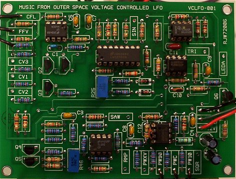
Voltage Controlled LFO PCB Populated
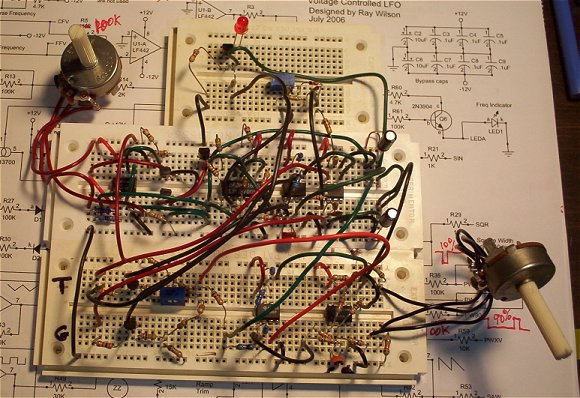
Voltage Controlled LFO on the Breadboard
Voltage Controlled LFO Front Panel and Wiring PDF

Voltage Controlled LFO Project Parts List
- Using 1% metal film resistors everywhere will reduce temperature related drift.
- Where 1% metal film is specified 5% carbon comp will work but with more temperature drift.
- Usually biFET amps (quads, duals, singles) can be replaced with an equivalent from another manufacturer.
- Capacitors can be film, ceramic, or silver mica.
- LM13700 subs (if applicable) (LM13600, NE5517, AU5517, NTE870, NJM13600/13700).
VC-LFO Project Parts List
If you are using +/-15V the following resistor values change. Keep it in mind when ordering parts.
R40 = 9.1K
R45 = 10K
R2 = 10K
Capacitors
C11 (main oscillator integrator cap) should be a temperature stable type of cap (polystyrene, polycarbonate, etc.).
All others can be ceramic or film.
Trimmers
Look over the board in relation to how you plan to mount it and decide what type of trimmers will fit your packaging (top adjust, side adjust, etc).
| Qty. | Description | Value | Designators |
|---|---|---|---|
| 1 | LF442 or TL072 Dual Op Amp | LF442 or TL072 | U1 |
| 1 | LM13700 Dual gm OpAmp | LM13700 | U3 |
| 4 | TL082 or TL072 Dual Op Amp | TL082 or TL072 | U2, U4, U5, U6 |
| 3 | 2N3904 | 2N3904 | Q1, Q2, Q6 |
| 1 | 2N3906 | 2N3906 | Q3 |
| 2 | MPF102 | MPF102 | Q4, Q5 |
| 2 | 1N914 Sw. Diode | VALUE | D1, D2 |
| 1 | LED | LED | LED1 |
| 3 | Potentiometer | 100K | R1, R4, R37 |
| 2 | Resistor 1/4 Watt 1% | 20K | R38, R43 |
| 2 | Resistor 1/4 Watt 5% | 4.7M | R10, R63 |
| 3 | Resistor 1/4 Watt 5% | 47K | R48, R54, R55 |
| 1 | Resistor 1/4 Watt 5% | 680K | R16 |
| 1 | Resistor 1/4 Watt 5% | 9.1K | R45 |
| 11 | Resistor 1/4 Watt 5% | 100K | R5, R7, R12, R13, R27, R30, R33, R36, R42, R56, R61 |
| 11 | Resistor 1/4 Watt 5% | 10K | R3, R11, R35, R40, R41, R44, R47, R51, R52, R58, R59 |
| 1 | Resistor 1/4 Watt 5% | 110K | R28 |
| 1 | Resistor 1/4 Watt 5% | 120K | R17 |
| 2 | Resistor 1/4 Watt 5% | 15K | R32, R50 |
| 1 | Resistor 1/4 Watt 5% | 180K | R23 |
| 6 | Resistor 1/4 Watt 5% | 1K | R15, R21, R26, R29, R53, R57 |
| 1 | Resistor 1/4 Watt 5% | 1M | R34 |
| 1 | Resistor 1/4 Watt 5% | 270K | R18 |
| 2 | Resistor 1/4 Watt 5% | 27K | R31, R62 |
| 2 | Resistor 1/4 Watt 5% | 2K | R14, R19 |
| 1 | Resistor 1/4 Watt 5% | 2M | R24 |
| 2 | Resistor 1/4 Watt 5% | 30K | R39, R49 |
| 1 | Resistor 1/4 Watt 5% | 39K | R22 |
| 1 | Resistor 1/4 Watt 5% | 3M | R8 |
| 3 | Resistor 1/4 Watt 5% | 4.7K | R2, R20, R60 |
| 1 | Trim Pot | 100K | R25 |
| 1 | Trim Pot | 2K | R46 |
| 1 | Ceramic or Film Capacitor | .02uF | C11 |
| 6 | Ceramic or Film Capacitor | .1uF | C3, C4, C5, C7, C8, C9 |
| 1 | Ceramic or Film Capacitor | 100pF | C1 |
| 2 | Ceramic or Film Capacitor | 10pF | C10, C12 |
| 2 | Electrolytic Capacitor | 10uF | C2, C6 |
Miscellaneous
- 1/16" Thick aluminum plate for mounting the pots and switches.
- Unit is typically mounted in a synth case with other synth modules.
- Assorted hardware 1" 6-32 nuts and bolts, 1/2" #8 wood screws, etc
- Knobs for potentiometers, wire and solder.
- Digital Volt Meter and a Signal Tracer or oscilloscope for testing.