Ray Wilson authored this content while he was actively running MFOS as the founder and resident genius.
We retain the content because it reflects a valuable point of view representing that time and place.
Article by Ray Wilson
Table of Contents
Pseudo Voltage Control Anyone?
Back to topSo you want to add some voltage control to your WSG huh? Well you can but it WILL NOT BE 1V/Oct it will simply be higher voltage results in higher frequency, lower voltage results in lower frequency. It will provide some new twists for your weird sound making though. The MFOS sequencer might be a great next project for you to undertake. It can then be used for the source of modulation voltage and gate input. An LFO could also be used.
Below are some suggested mods. You can kludge these in to the kludge area or build them on a small perf daughterboard. Here is an explanatory YouTube produced at Ray Wilson studios in downtown Parker, CO.
Pseudo-CV Control
Essentially the mods are all similar. They use a N-Channel JFET as a voltage controlled resistor in order to change the frequency of the WSG's oscillators. In the case of the filter one is used to affect the filter's cut-off frequency. The source and drain are in series with a 4.7K resistor. The 4.7K limits the lowest resistance this circuit applies across the points connected to the WSG's control terminals. The 1M resistor holds the gate at ground in the event you disconnect the CV input. Without being held at ground the gate would float and the source to drain resistance would fluctuate wildly based on whatever electrical field happens to get to the gate. The 300K resistor basically protects the gate by limiting the current it sees to micro-amps. As you can see the same circuit appears again and again but is connected across different parts of the WSG's circuitry. Just solder the additional wires to the WSG board at whatever convenient location you find that corresponds to the circuit points cited. For example I connected the wires from the mod for WD1A and WD2A to the ends of R7 and R14 but I could have soldered them to the bottom of the WD1A and WD2A pads. Either place is fine.
Filter WUP WUP WUP or CO CO CO
OK I agree that the terms "WUP WUP WUP" and/or "CO CO CO" are not super technical but they kind of describe the sound you get when the filter is being controlled by one or the other preset A-D curves provided by the two networks that you can switch in and out. You might just add one or the other (both are not mandatory). The gate from the MFOS 10 Step Sequencer (or 16 step for that matter) fed to this WSG mod will let you control the filter C.O. frequency with one of two envelopes. By setting some of the gate switches on and some of them off you can get some very cool rhythmic patterns. Note that when the Coarse Cut-Off is turned all the way up this mod is essentially out of the circuit. So turn it down some when you want to hear the effect of this mod.
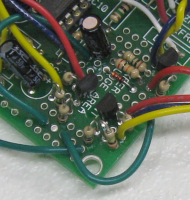
A photo of my kludge taken through the Hubble (before the repairs).
Here is a picture of my board post-modification. If you are more frugal with the kludge pads than I was I'd bet you can get all of the mods in there. Mount resistors vertically and make every pad count. Bear in mind that the pads in the center are connected to the next row of dots by lands. Take a good look at the underside of the board to see what I mean. Don't assume that all of the pads are separate or you will end up kicking yourself (not that I kicked myself... well I didn't... perhaps a gentle goad...). To connect adjacent component leads that are in non-connected pads when you need to just bend them toward one another or twist them together and then solder them. Kludging with finesse takes practice. When you get really good at it no one will even know it's a kludge.
A Bit Of Explanation Regarding Using Some Jacks.
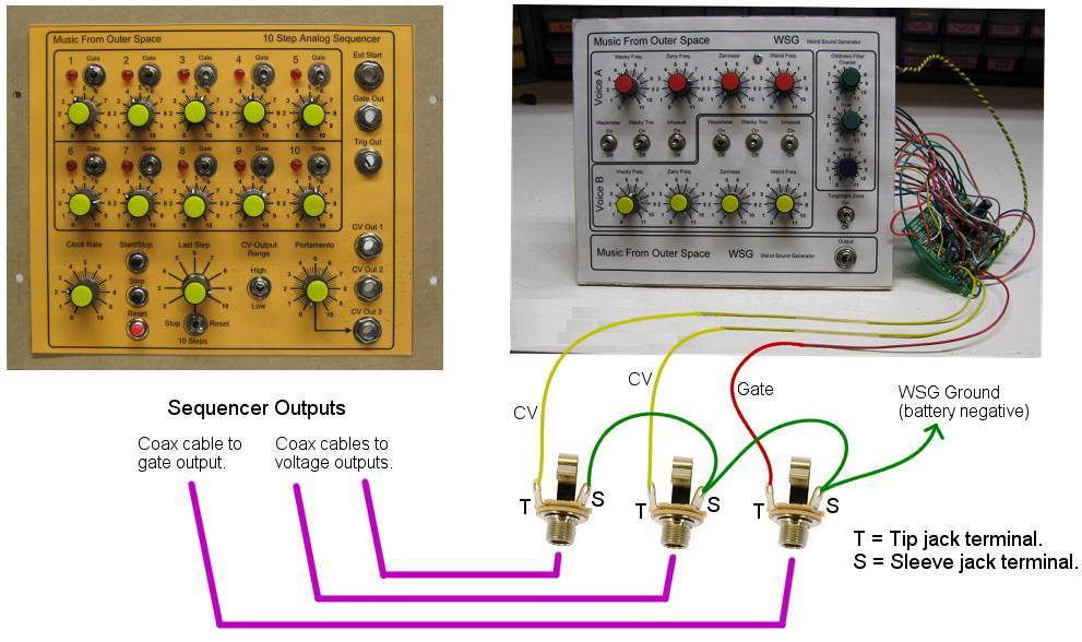
Here is how you would add some jacks to your current WSG to make connecting to the sequencer easier. If you decided to add the mod to control both the Weird Oscillators and the Wacky oscillators you would have four CV connection points instead of just the two shown here. The red wire is for the gate modification and connects to the sequencer's gate. You could mount these jacks in your WSG box on a metal (or whatever material you like) plate. Since I show all of the jack grounds connected together it won't matter if the mounting plate is conductive. Now you can just use your coax patch cables to connect up the sequencer and the WSG. Hey... your starting to get closer to that modular you always wanted. Have fun :-)
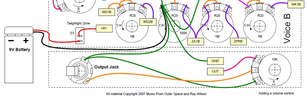
Adding a Volume Control
Back to top
Here is how you would add a volume control to the output of the WSG. As you can see the OUT goes to one of the terminals of the volume control pot (10K linear or audio taper pot). The other outer terminal is grounded and the center terminal connects to the "hot" or "tip" connector on the jack. Now you can turn the volume of your WSG down ... reluctantly of course.
Power On Indicator LED
Back to top
Here's how to add an LED to show that the WSG is turned on. The power switch applies power to the LED along with the WSG circuit. The LED is wired so that the 1K resistor provides current limiting. The LED's cathode goes to ground. You can go lower in resistance to make the LED brighter but your battery will become depleted faster.
Channel A Zany Frequency Indicator LED
Back to top
Here's how to add an LED to show the rate of the A Channel Zany Frequency. The LED is wired so that the 1K resistor provides current limiting. The LED's cathode goes to ground. You can go lower in resistance to make the LED brighter but your battery will become depleted faster.
Channel B Zany Frequency Indicator LED
Back to top
Here's how to add an LED to show the rate of the B Channel Zany Frequency. The LED is wired so that the 1K resistor provides current limiting. The LED's cathode goes to ground. You can go lower in resistance to make the LED brighter but your battery will become depleted faster.
Channel A Zany Oscillator Trigger Out
Back to top
This mod will let you trigger other modules from your WSG. The triggers will be at the same rate as Channel A Zany frequency. Whether or not this will trigger your gear is dependent on how much voltage your gear's trigger input requires. The WSG can only put out a pulse that will be in the 5 to 7 volt range. You can increase the size of the capacitor to about 0.1uF but not much more to get a bit more amplitude in the pulse.
Channel B Zany Oscillator Trigger Out
Back to top
This mod will let you trigger other modules from your WSG. The triggers will be at the same rate as Channel B Zany frequency. Whether or not this will trigger your gear is dependent on how much voltage your gear's trigger input requires. The WSG can only put out a pulse that will be in the 5 to 7 volt range. You can increase the size of the capacitor to about 0.1uF but not much more to get a bit more amplitude in the pulse.