Sound Lab Mini-Synth PLUS Panel Wiring
Ray Wilson authored this content while he was actively running MFOS as the founder and resident genius.
We retain the content because it reflects a valuable point of view representing that time and place.
Article by Ray Wilson
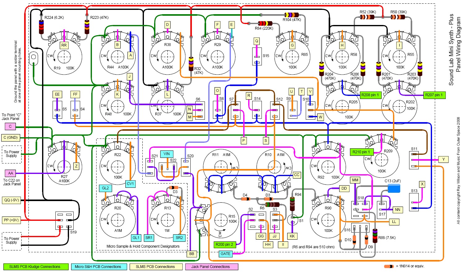
| Sound Lab Mini-Synth PLUS Panel Wiring Diagram (Rear View) |
|
Click this image for a larger one or click here for a PDF version. Wire the
points on this diagram to: the corresponding points on the PC Board (including kludged connections), the
MICRO SAMPLE AND HOLD PC Board, and the jack panel. For connecting the flying components I use a variety of
methods including, shrink tubing, nylon wire ties and nylon wire tie anchors, terminal strips, etc. The main point
is to make sure the connections are secure and that they don't short to anything. Also if you use 1/2 watt resistors for
the flying components they have thicker more stable leads. Note the key at the bottom of the diagram. The various colors
indicate where the point gets connected:
Pot values with an A (A100K for example) are audio taper. All others are linear taper.
|
|
| New connections for the new "Micro Sample n' Hold June 2011" are shown on this drawing. | |
 |
|
|
Connections for the obsolete "Micro Sample n' Hold" are shown on this drawing for reference. This board was updated quite a while ago but if that is the version you have here is the hook-up. |
|
 |
|
|
Sound Lab Mini-Synth PLUS Panel Legend (Front View)
User Contributed Panel Designs
Click this image for a PDF. In order to print it in the proper size set the PDF print setup to "legal size (11" x 14")" paper.
|
|
| Panel with changes related to new "Micro Sample n' Hold June 2011" are shown on this drawing. | |
 |
|
|
Sound Lab Mini-Synth PLUS Jack Panel Wiring Diagram
|
|
 |
|
|
Sound Lab Mini-Synth PLUS Battery Connection
|
|
 |