Ray Wilson authored this content while he was actively running MFOS as the founder and resident genius.
We retain the content because it reflects a valuable point of view representing that time and place.
Article by Ray Wilson
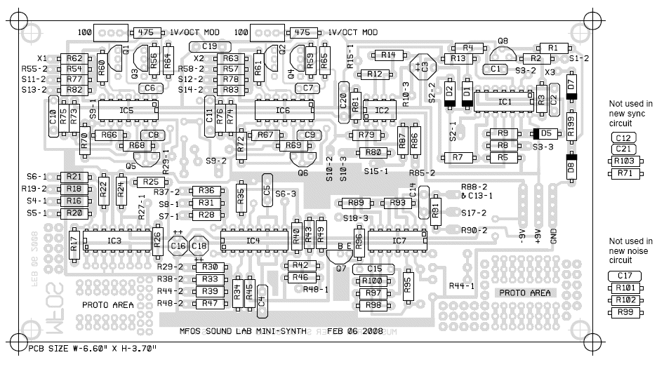
PC Board Parts Layout Illustrations
|
PC Board Parts Legend Please note that the components that are no longer used in the Sound Lab Mini-Synth PLUS are shown on the side for clarity. The PC Board still has these legends on it. Just leave these components off if building anew or remove them if you are modding an existing Sound Lab. |
|
 |
|
|
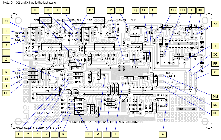
PC Board To Front Panel Wiring
The front panel diagram has letters that correspond to these letters. Connect a wire (of sufficient length) from
the board to the panel at each pair of corresponding lettered points. There are two points "W" and "E" that are shown
below on the Inverting Level Shifters to Front Panel Wiring drawing. Remember to connect those too.
|
|
 |
|
|
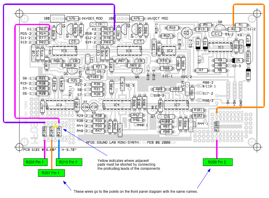
Fine Tuner Support Kludge To Front Panel Wiring The fine tuners mixer resistors, R209 "VCO-2 Mod VCO-1" resistor and the resistor used in switching the Sample & Hold gate to the AR Generator are shon here. Remember to put the components as shown so that the various mods don't interfere with one another. |
|
 |
|
|
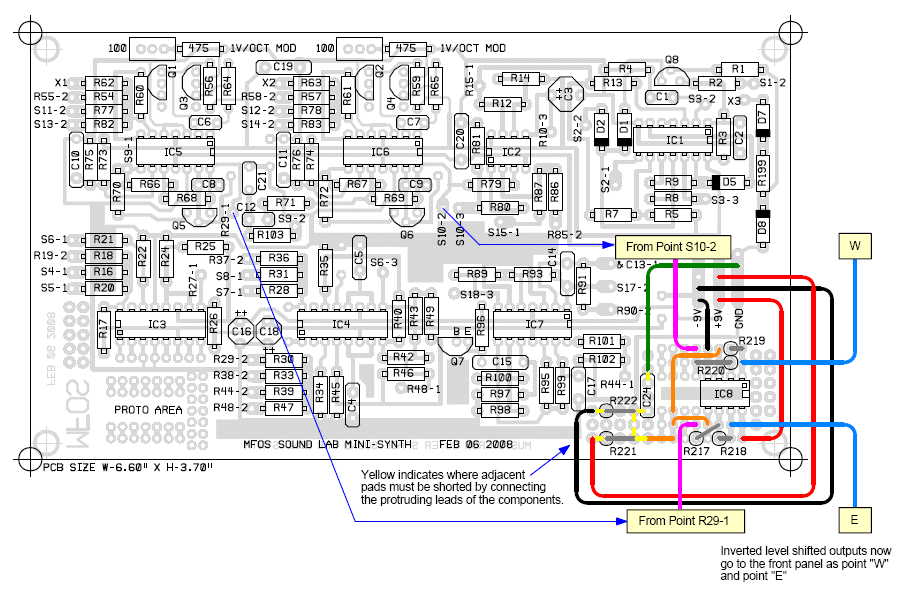
Inverting Level Shifters to Front Panel Wiring In addition to the panel connections shown above in the PC Board To Front Panel Wiring section above you need to connect a wire (of sufficient length) from the board to the panel at points "W" and "E" shown here. These points are the inverted, level-shifted (formerly ramp now sawtooth) oscillator outputs. |
|
 |