Ray Wilson authored this content while he was actively running MFOS as the founder and resident genius.
We retain the content because it reflects a valuable point of view representing that time and place.
Article by Ray Wilson
Table of Contents
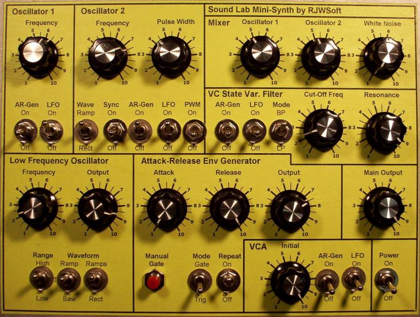
My Sound Lab Mini-Synth Front Panel
Back to Top
 Click image for a larger view |
I took a cue from Jorgen Bergfors and made my front panel by laminating a piece of paper onto a 1/16 inch thick aluminum panel. I wrote a program to let me easily lay out front panels and then I laser printed the design onto some bright green paper. The adhesive I use to apply the paper onto the aluminum is acrylic polymer (you buy it in art stores). I coat the aluminum and the back of the paper and then while both are still wet I apply the paper to the aluminum. I then brush polymer onto the front of the paper so that the panel is dirt and water proof. The result is very useful and much nicer looking than my previous efforts to scribble with a Sharpee pen. |
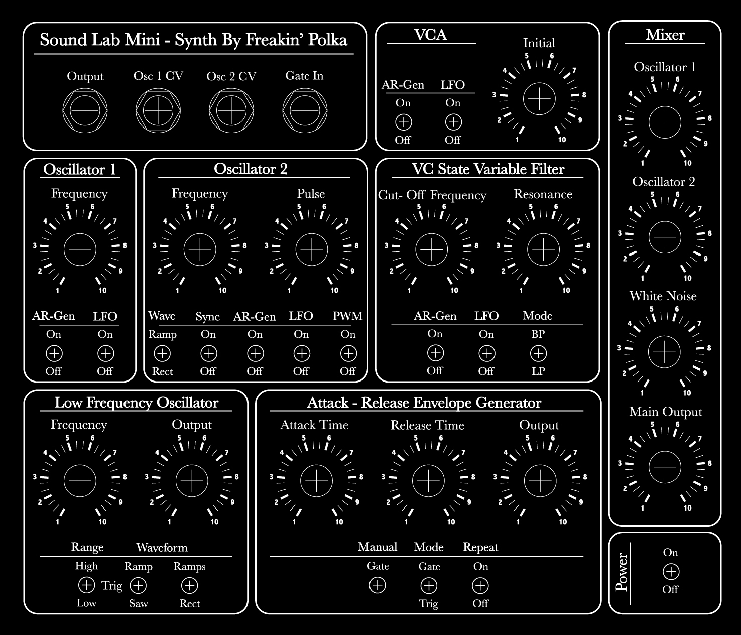
Suggested Front Panel Layouts for Sound Lab Mini-Synth
Back to Top
 Click image for a larger view |
When I print from my panel design program I don't get the jaggies you see here. I included a function to output a BMP to the clipboard so I can post drawings on the web. This
template is actual size and will work even if it is a bit jaggie. I have provided a X2 version that you may be able to use to get a less jaggie reduction. X1 Scale X2 Scale Front Panel PDF |
||||||||||||
Front Panels contributed by other buildersPlease bear in mind that if you use another front panel design that the panel wiring diagrams I provide will not apply. You will be on your own with the panel wiring. I suggest that you make your own panel wiring drawing and carefully transpose the connection information. Good wiring. |
|||||||||||||
|
|||||||||||||
LIST OF PARTS MOUNTED ON THE FRONT PANEL AND NOT THE PC BOARD
Back to TopThese parts are not mounted on the PC board they are mounted on either the control panel or the input/output panel.
Pots: R44, R38, R29, R85, R58, R55, R48, R37, R27, R15, R11, R10, R92, R90, R19
Switches: S6, S8, S7, S15, S14, S12, S9, S10, S13, S11, S19, S5, S4,S 2, S3, S1, S18, S16, S17
Resistors: R104, R84, R52, R50, R32, R41, R94, R6, R88, R23
Diodes: D4, D3, D9, D10
Caps: C13, C22
Jacks: Gate In, Osc-2 CV, Osc-1 CV, Output
Sound Lab Mini-Synth Panel Wiring [Click for PDF]
Back to Top
| I found a 1/16 inch thick aluminum plate big enough for the front panel. I drilled it, cleaned it and then labeled it (as described above). After this I installed the pots and switches. Use this drawing to wire the front panel. Use a flexible stranded wire for best results. There is no rhyme to the color scheme but I think I did stay with red as +9V, black as -9V, and green as ground throughout. It should go without mentioning but who knows you may be very new to the synth scene. You need to strip the ends of the wire and solder them to the termination points (the places where wires touch pots, switches and other components). |
View Rev 000 Version (here for reference only)
Sound Lab Mini-Synth Panel Wiring Diagram With Wiring Labels [Click for PDF]
View Rev 000 Version (here for reference only)
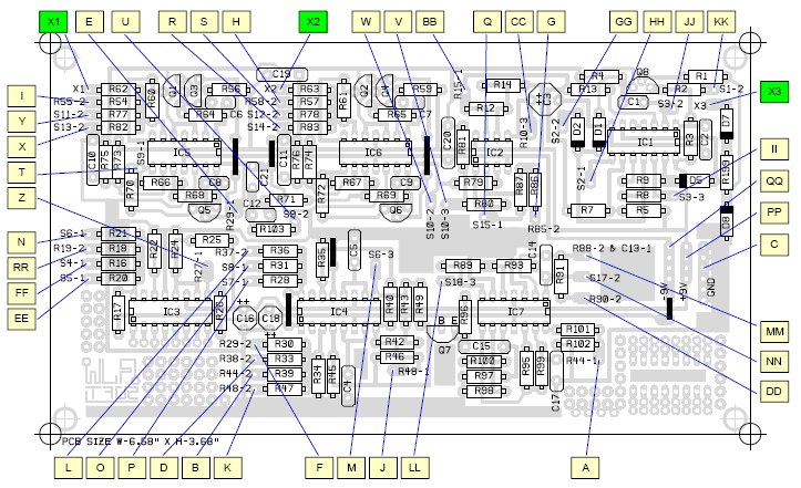
Sound Lab Mini-Synth Parts Layout With Wiring Labels
EXCEPT FOR X1, X2, and X3 shown below which are related to both the circular schematic references AND the PCB connection points
|
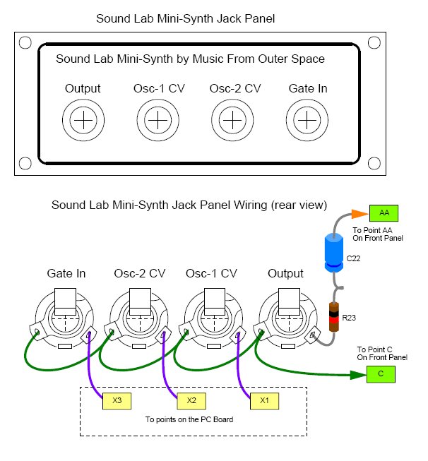
Sound Lab Mini-Synth Input/Output Connections [Click for PDF]
EXCEPT FOR X1, X2, and X3 shown below which are related to both the circular schematic references AND the PCB connection points
| The sound lab can be controlled by external equipment (keyboards, sequencers, etc). I recommend that you don't apply voltage greater than 9 volts to the inputs or you may damage the components. I used 1/4" jacks for all in/out connections but you can use smaller ones if you want. If you can't find a 1uF non-polarized cap then just use two 2uF electrolytic caps connected back-to-back (i.e. connect the negative terminals of the two together and use the positive terminals as the cap leads). |
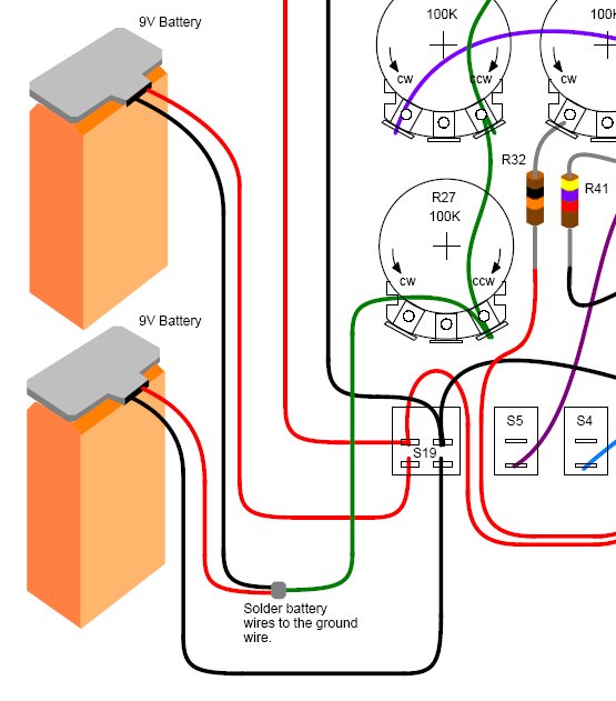
| The sound lab is powered by 2 nine volt batteries connected as +/-9V as shown here. Radio Shack sells 9V battery clips (Radio Shack #s 270-325 or 270-324) |
Kit Notes
Back to Top
Kits come with SPDT switches which work perfectly as SPST
I send all Single Pole Double Throw Switches in kits because they also serve perfectly as SPST switches. As you can see in this image the switch has three terminals. The middle terminal is common and is connected to either of the outer terminals depending on the position of the switch bat. The terminal that is opposite of the way the switch bat leans is the terminal in contact with the middle terminal. Either outer terminal can be used.
Battery Snaps
We ship two types of battery snap. One has red and black wire (type 1) and one has two black wires with one of them imprinted with a white broken stripe (type 2). With the red and black type the red is the positive connection. With the two black wire type the one imprinted with a white broken stripe is the positive connection.
The type 2 snap (two black wire) has "zip" wire which can be separated easily by simply pulling the two wires apart near the stripped end.
Type 1 and 2 battery snaps. |
Type 2 zip wire separated. |
|---|---|
 |
 |
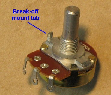
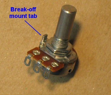
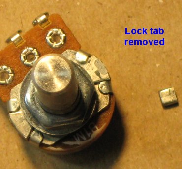
How To Remove Break-off Lock Tabs From Your Potentiometers
If your pots have little tabs on them you will need to remove them so that you can mount them to your faceplate. It is really easy to do. Carefully snap off the little tab near the pot body and voila it's done. Some kits come with larger pots and some kits come with smaller pots. The smaller pots are at times more expensive than the larger pots. They're all good quality pots and they all work the same way.
Regular Sized Pots |
Smaller Sized Pots |
|---|---|
| This is the break-off lock tab which can be used to keep the pot from turning when you turn the pot shaft but tightening the mounting nut works just fine. If you have the wherewithal to drill little holes for these pesky things... be my guest. If not... read on. | |
 |
 |
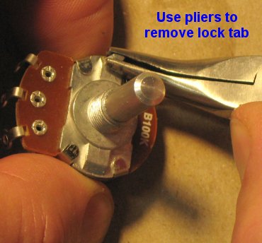
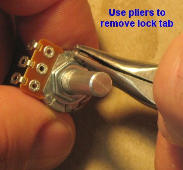
| Using pliers, grasp the tab as low on it as you can and then gently twist the pliers outward. I told you it was easy. | |
 |
 |
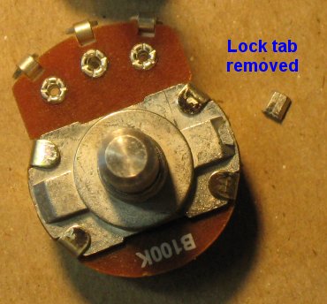
| The little broken off tabs look like this. Now you can mount your pot without the little tab getting in the way. | |
 |
 |