Weird Sound Generator Reborn (and with a PCB no less)

Ray Wilson authored this content while he was actively running MFOS as the founder and resident genius.
We retain the content because it reflects a valuable point of view representing that time and place.

Article by Ray Wilson
Back to "Music From Outer Space" Analog Synth Pages

Features

  • Makes Wacky, Zany, Weird, Unusual Sounds
  • Stimulates brain cell growth in humans and pets.
  • Exposure of fetus to Weird Sounds promotes genius and prodigy...ism.
  • Exposure of adolescents to Weird Sounds promotes respect and admiration for parents.
  • Exposure of octogenarians to Weird Sounds reduces flatulence.
  • Fun to do at lunch time, snack time, anytime (low in calories).
  • Fun to do at board meetings (or in boring meetings).
  • Low current consumption so you can make weird sounds for a long long time.

This project was personally endorsed by Albert Einstein who, while alive, looked into the future (as was his wont) and declared... "Zom day Zom vun iss goink to make a very veird zound generator. I would like to personally endorse it ahead of time." Not many people know this fact but now both of us do.


WSG Original Recipe (with this PCB)

The WSG Community Page (where it all began)

  New Trouble Shooting Tips

There is a 5 second delay when you turn the unit on.

Testing in the Weird Sound Labs has shown that there is a five second delay when the unit is first powered. This is due to the biasing network (R16, R17, and C8) charging up until the filter's bias input is happy. Nothing to be concerned about unless an alien is attacking and you know that if you could only hit it with that weird sound you found last night that it would be curtains for the alien. Then five seconds can seem like an eternity and we're sorry.

But I Really, Really... REALLY Want A Fully Formed Weird Sound Generator!

You want a WSG but for whatever reason you can't build it yourself. You have... no time to build.
  • You're a stock tycoon with a burning desire to make weird sounds but with all the buying low and selling high... no time to build!
  • You're in a band that needs weird sounds but your label is breathing down your neck to get an album out... no time to build!
  • You're a cowboy with a hankerin' to make weird sounds but the cows, the cows... no time to build!
  • You're a wealthy playboy that wants to make weird sounds while laying on the beach of the french riviera but between the women and the gambling... no time to build!
Your "no time to build a WSG problem" has just been solved! (Other problems... sorry we can't help.).

With all we are doing we eked out the time to help all of you make your weird sound making dreams come true. Now you can have weird sounds in the palm of your hand, ready to go, once you get a 9V battery, and an amplifier of some type. We suggest that at the time you order one, you go out and buy a nine volt battery and round up an amp and a guitar cable. Then when the WSG arrives you can power it up, attach it to the amp and start making weird sounds with no interruptions.

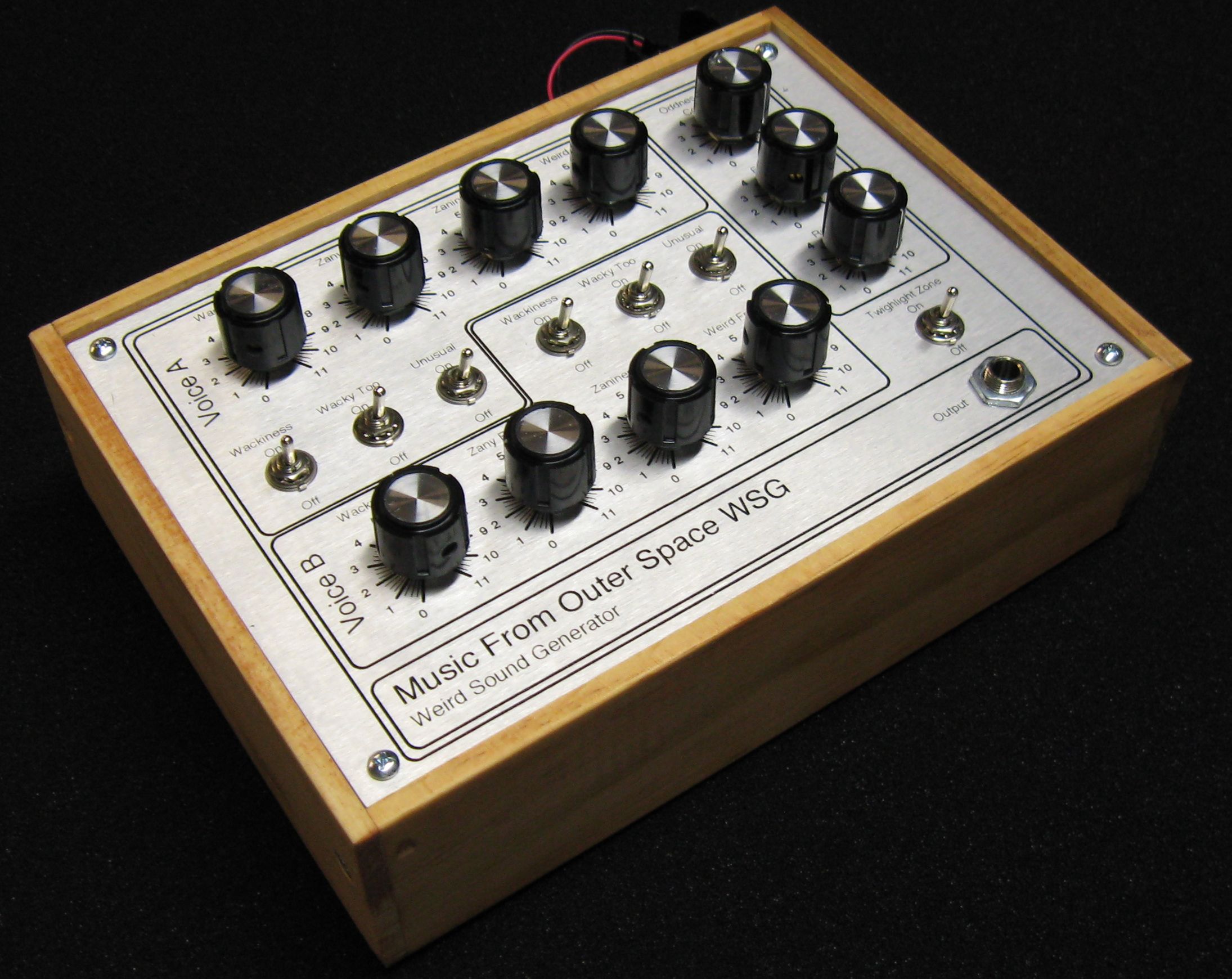
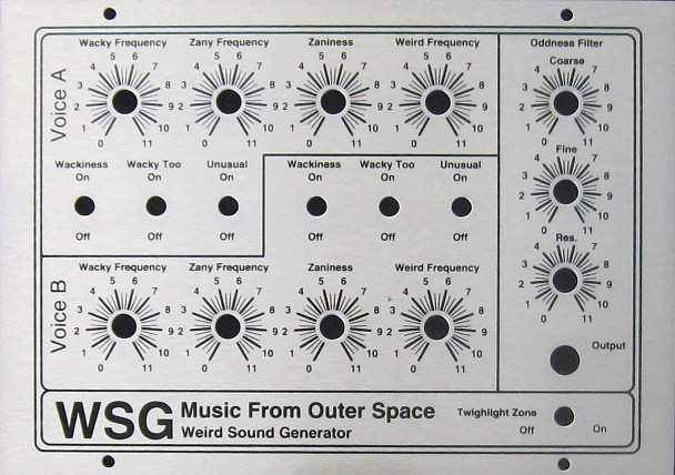
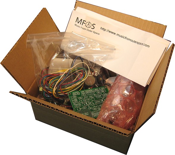
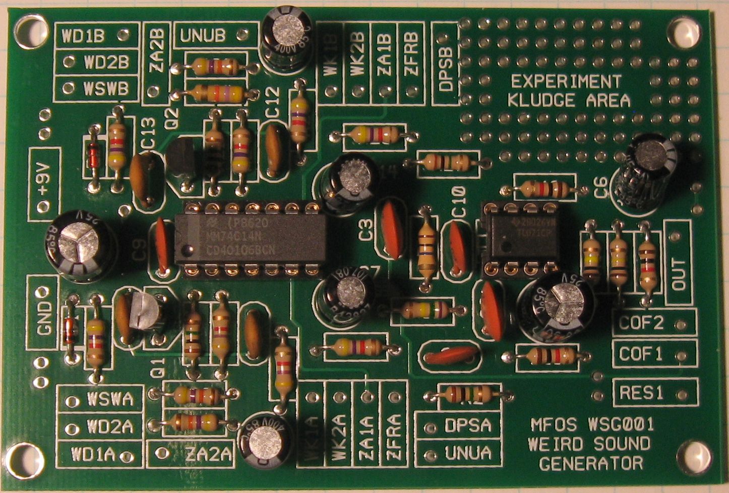
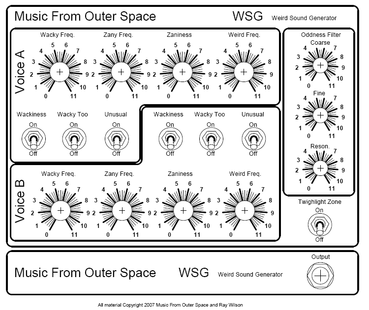
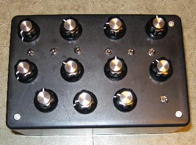
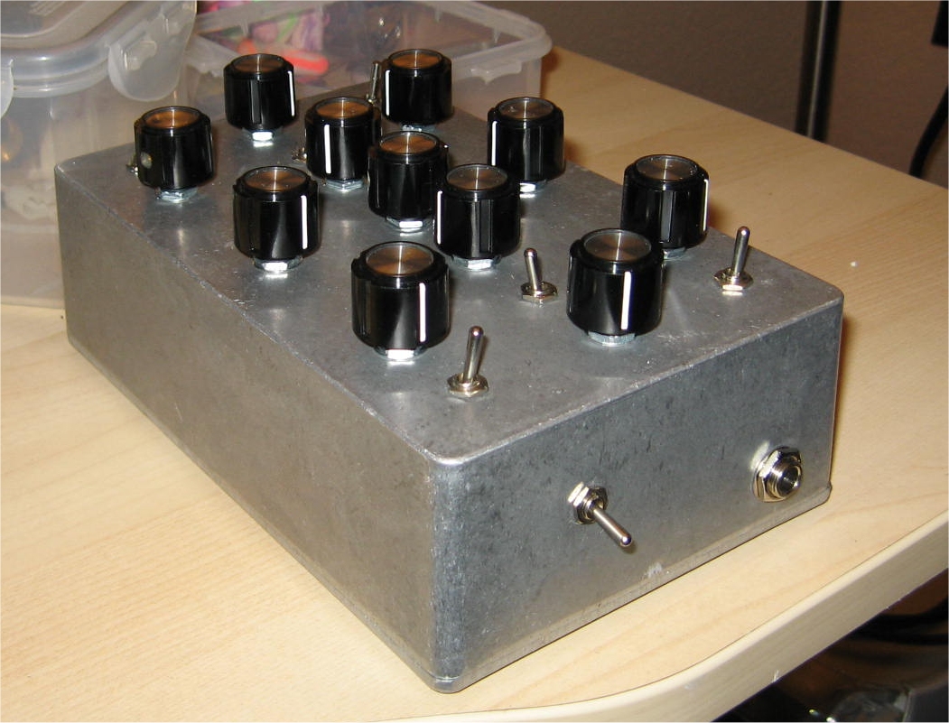
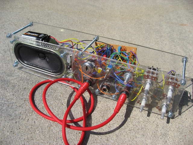
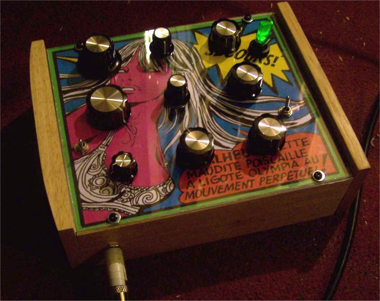
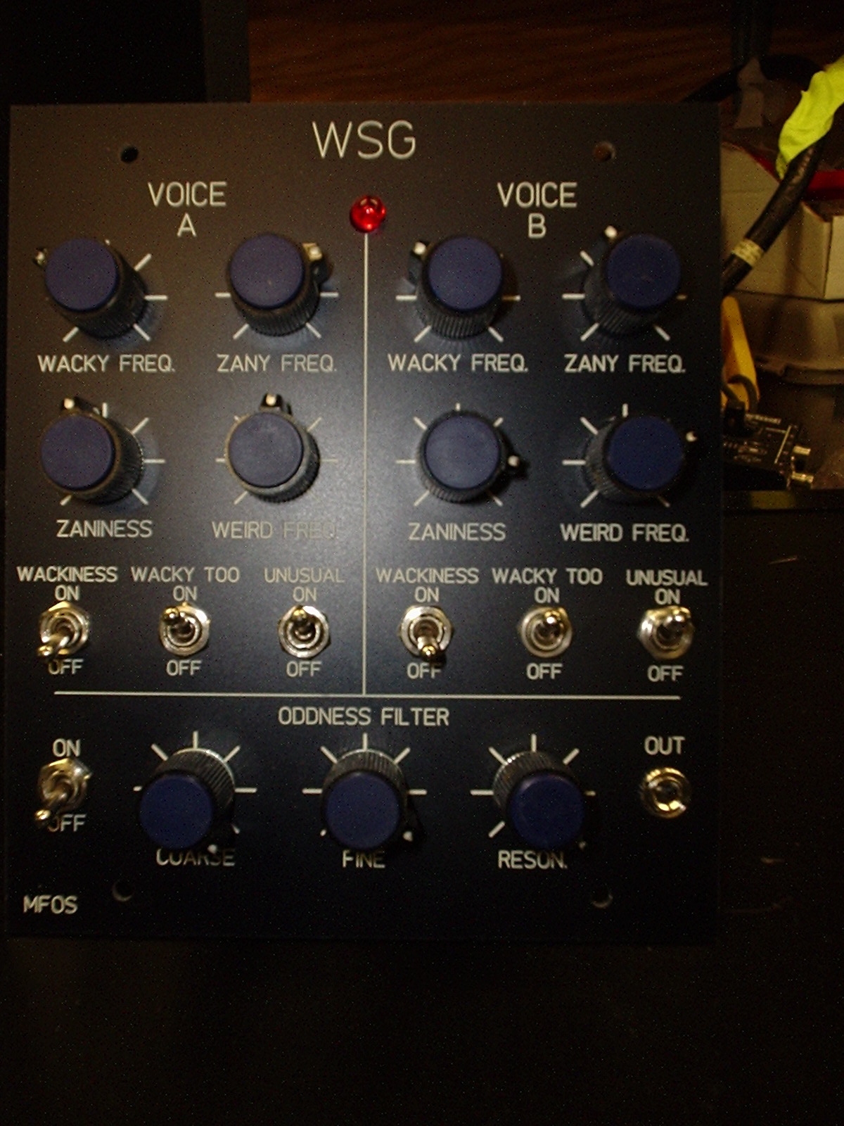
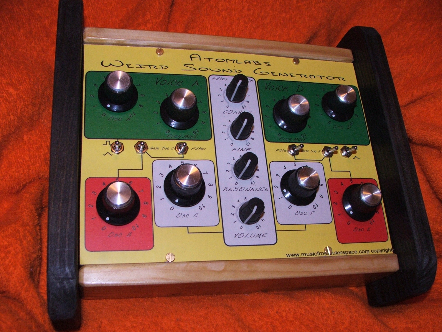
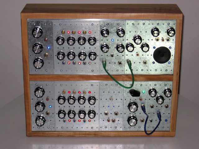
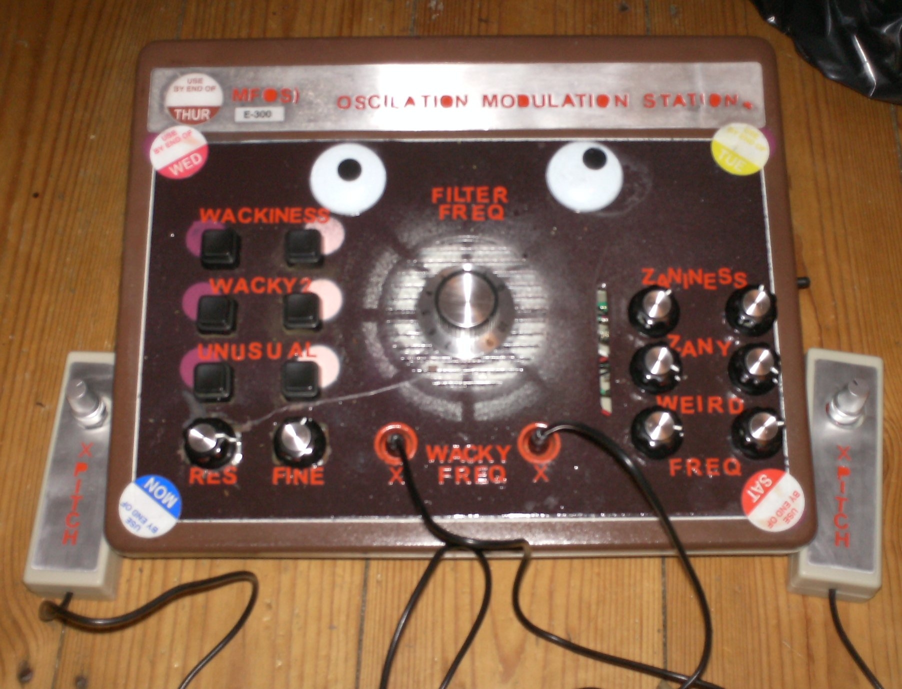
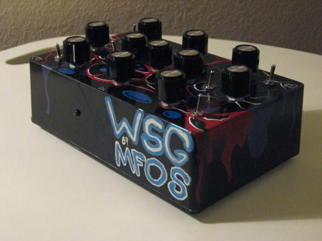
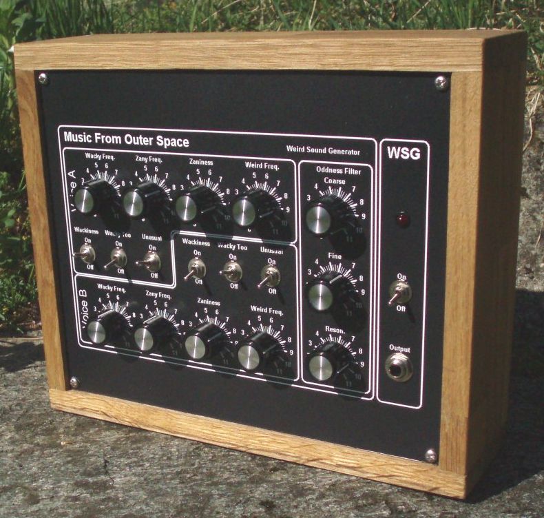
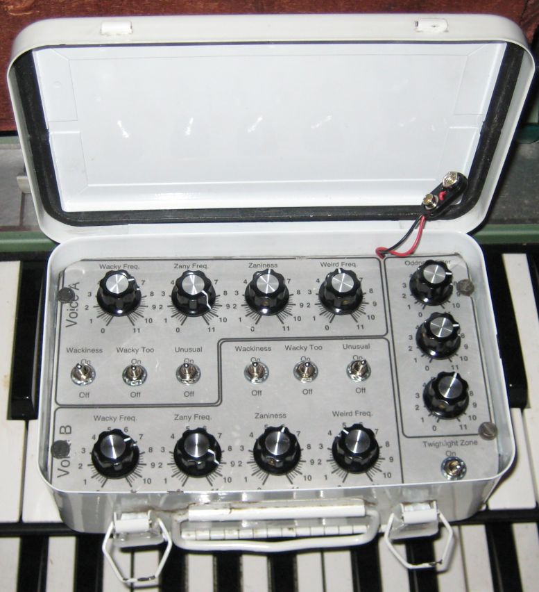
What does it look like you say?

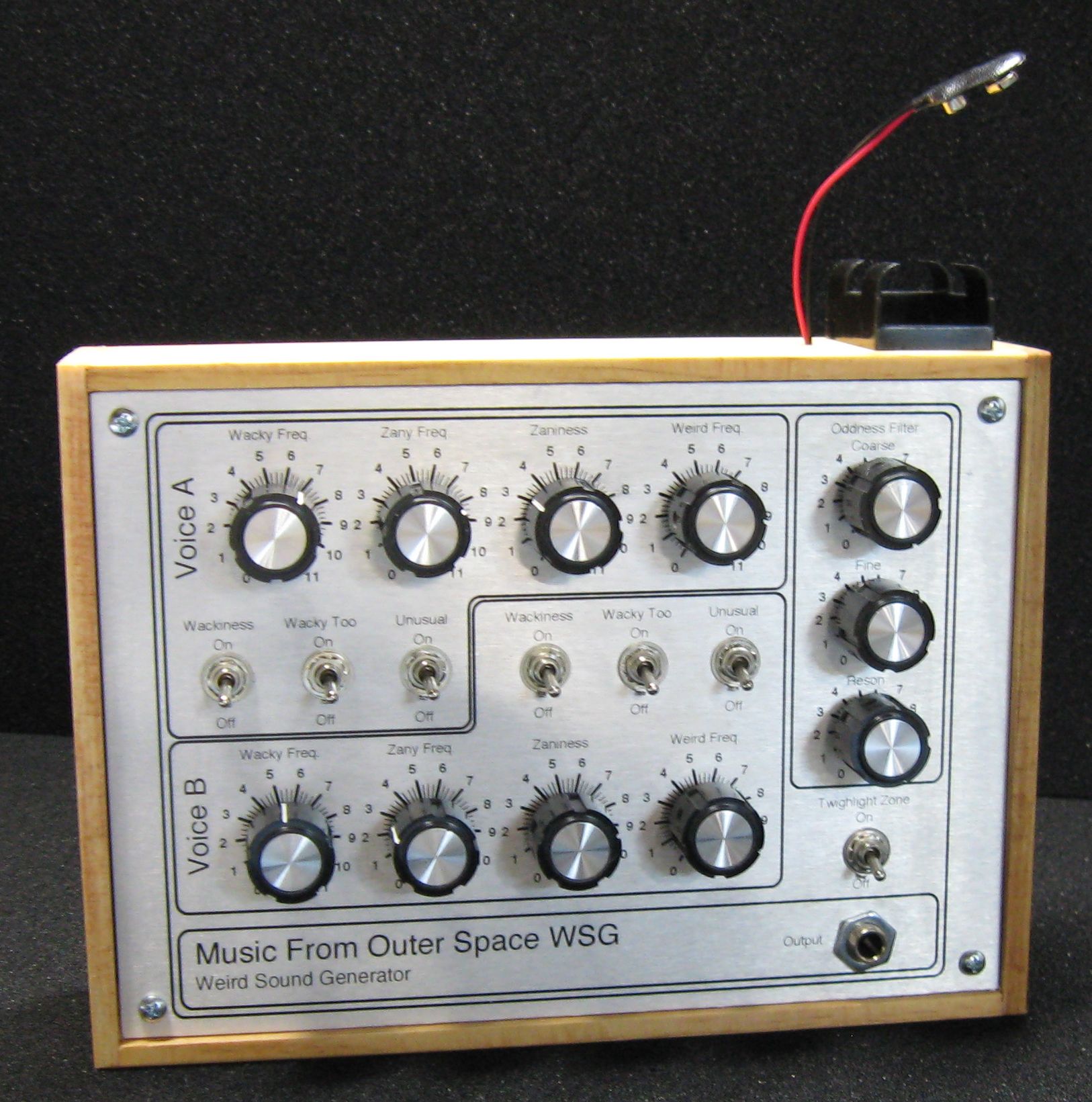
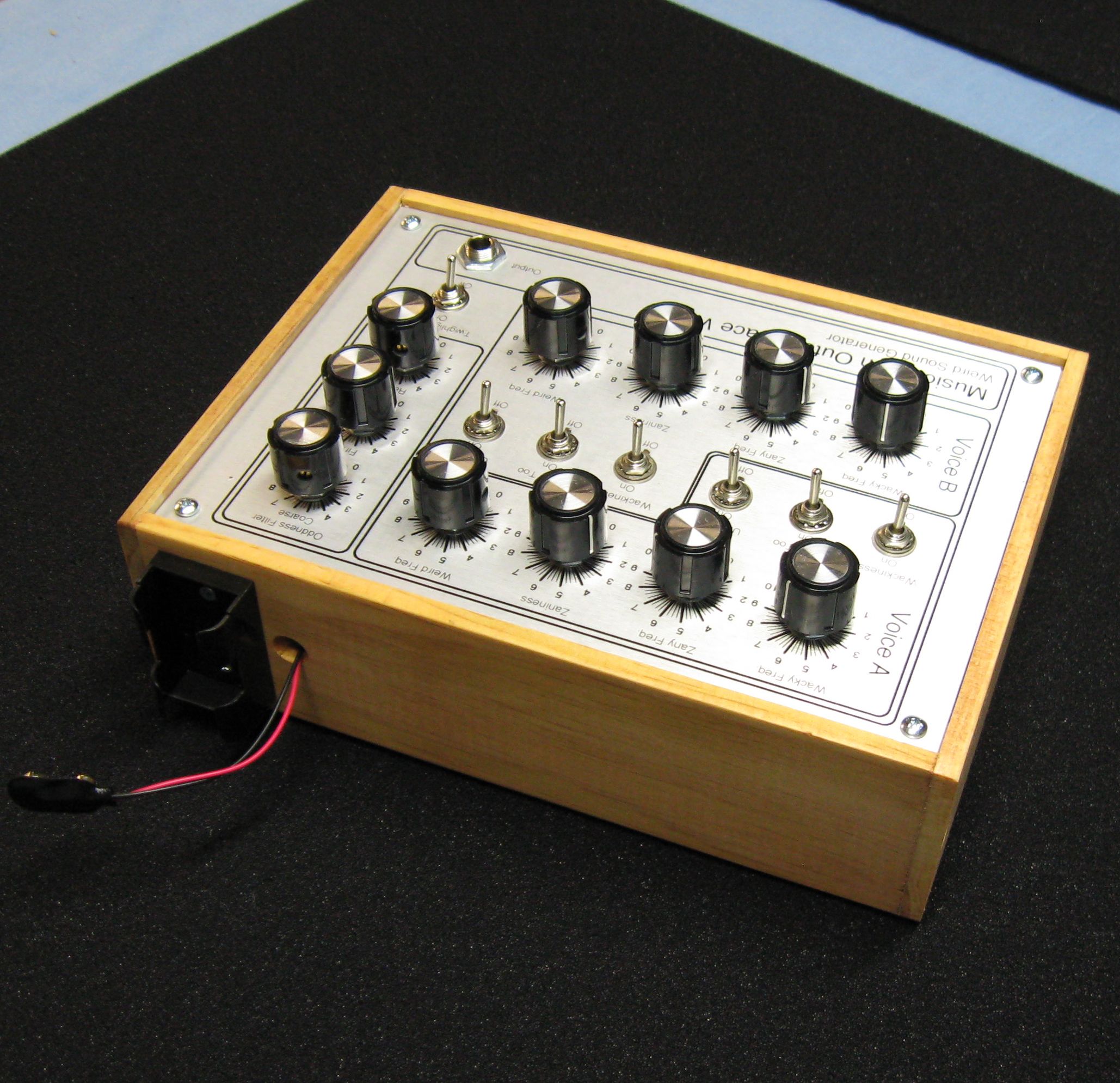
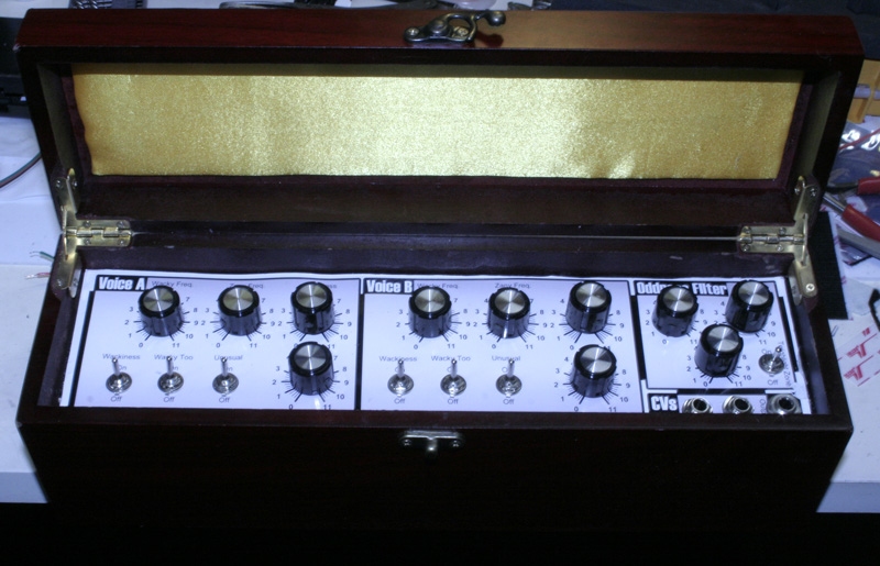
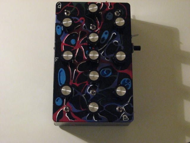
Look at the pictures below. It is built into a handmade wooden box by humans and not robots as you would suspect. Also each one is a little different in appearance. A scratch on the panel here, 
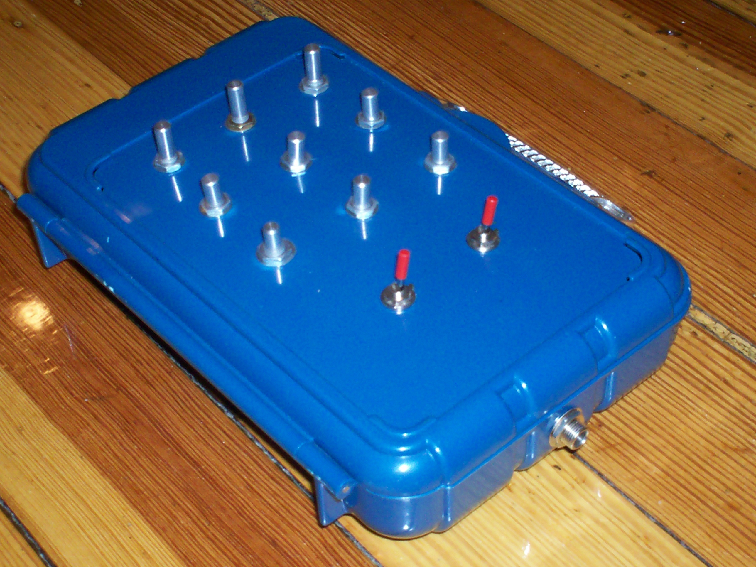
a nick in the wood there. They are by no means perfect carbon copies of one another. You are seeing a good example below and you can click on any of the pics for a HUGE photo. Look over the pictures REALLY WELL before you buy one. We test each one we make but hey if you have a problem with it within the first thirty days we will fix it for free if you ship it to us. You pay to ship it to us and we will pay to ship it back to you. Of course this is with the proviso that you did not drop kick it, deep fry it, back your car over it, etc. In those cases if you pay to ship it to us we will look it over give you an estimate and proceed if you agree to it. We're covering our butts here but we're reasonable types and don't want to stick anyone with a defective product so hey as the Beatles so aptly put it "We Can Work It Out".

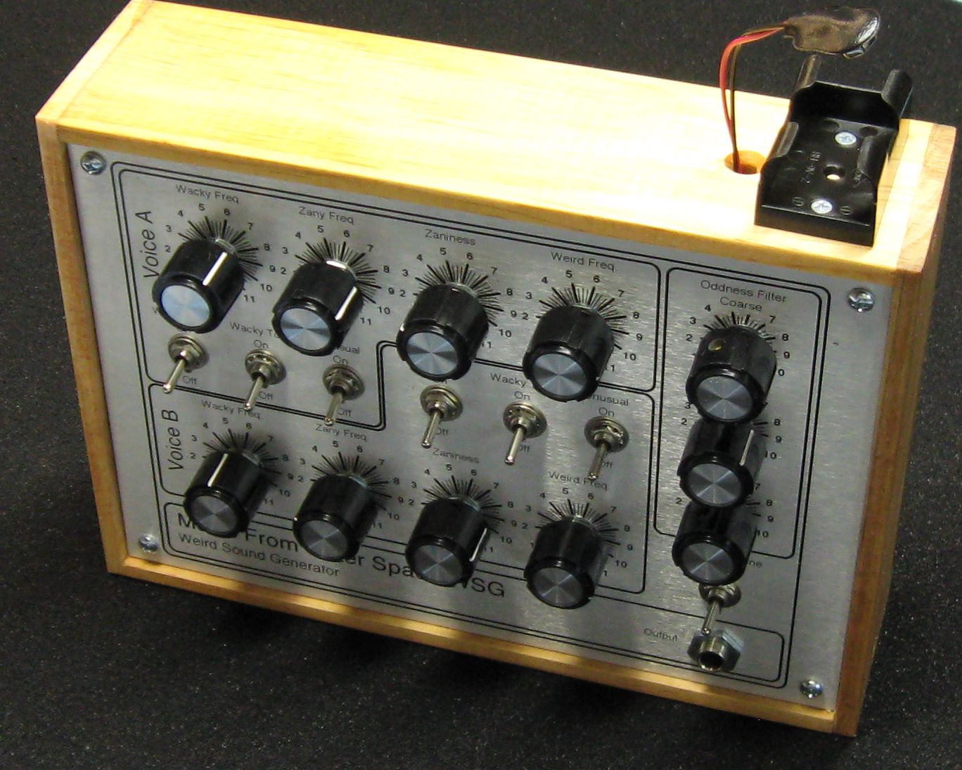
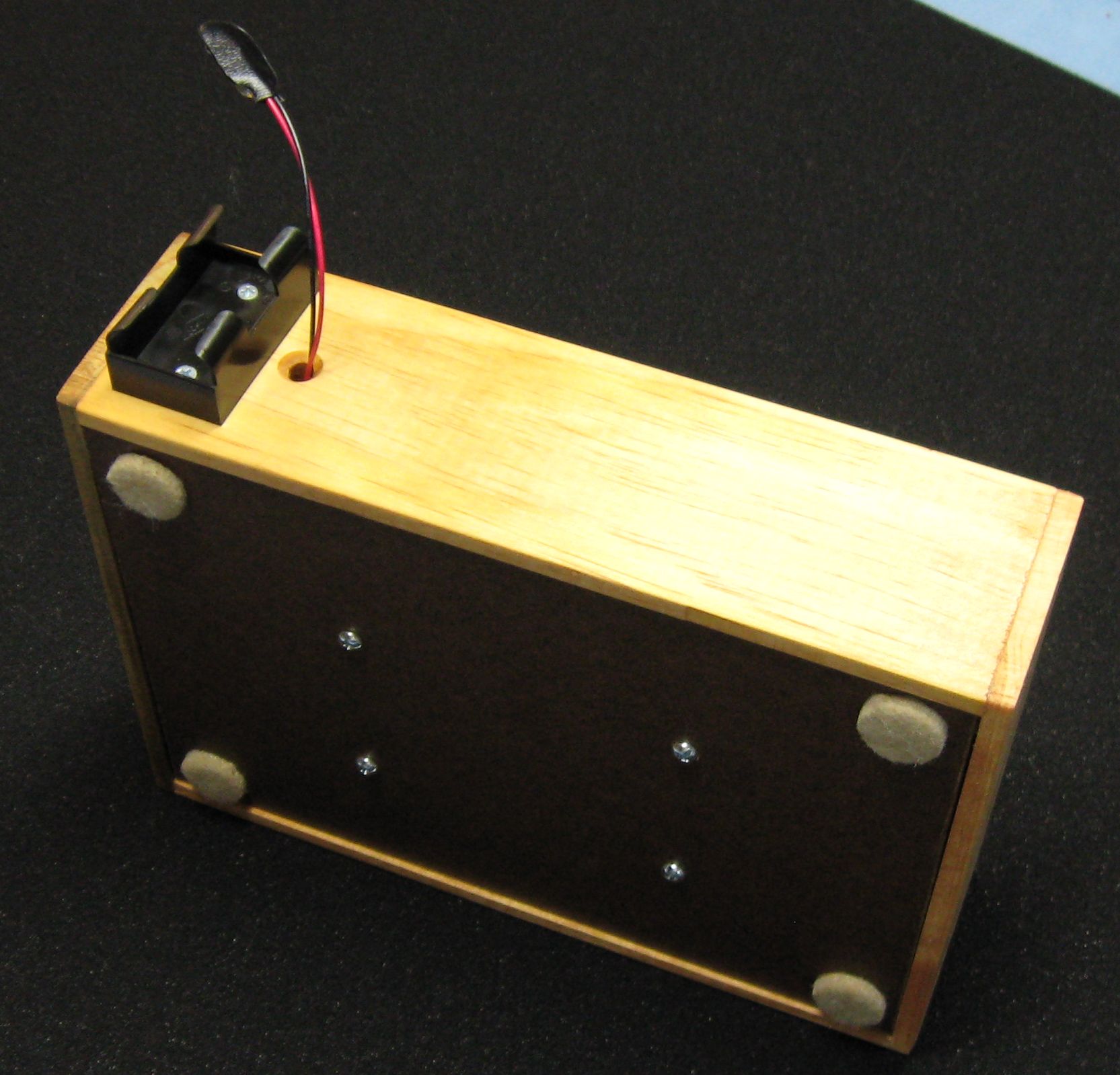
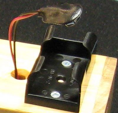
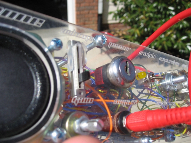
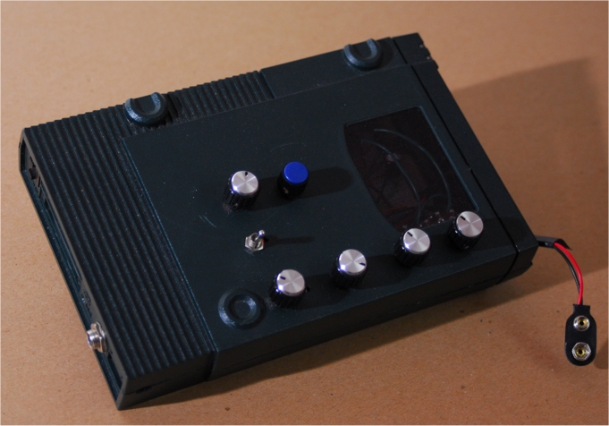
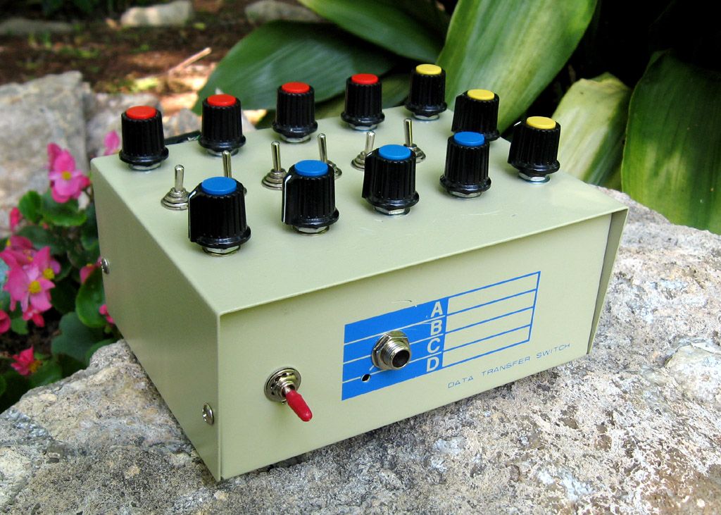
The battery holder is on the outside of the case.

Again look it over and only buy it if you like it. Don't let your peers pressure you into buying one if you aren't really sure it's something you want to do. Yes the battery holder is on the outside of the case. This battery holder is a little cantankerous and really likes to hold on to the battery so... The holder is right where you can get at it with no unscrewing, opening, whatever... We kind of like it there.

It does not come with a battery.

You must supply the 9V battery.

You need an amplifier to hear it.

You must supply the amplifier. We thought about maybe including a Fender Tube Twin Reverb just for the heck of it but the board of directors shot that down right away. Those naysaying nabobs of negativity.

Does it come with detailed instructions?

No it comes with very terse general instructions. As a matter of fact here they are in Word format: Fully Formed Weird Sound Generator Document

It aint cheap.

Sitting and repetitively making the same thing over and over and over again is not really our idea of a fun day at the beach... so we priced it so that if you really, really... really don't want to make one you can buy this one. But hey, everything you need to make it yourself is here on the page... now you have one more WSG option. Will they become collector's items..? Only time will tell. Studio and station managers these things are great for making odd attention getting bumpers. And remember... if you don't spend your budget this year... you're getting less next year... am I right or am I right...?
They can be purchased via the PayPal shopping cart below.


Give your Wacky, Zany, Weird, Odd Sound Generator that "professional" look

When you show up at the board room of your next stock holders meeting with a weird sound generator built into a shoebox, don't count on that elusive promotion you've been tacitly pursuing. However, if you show up with your WSG built into a nice case with this professionally manufactured front panel with a silk screened legend don't be surprised if you are asked to stand and open the meeting with a recitation of the company mission statement while accompanying yourself on the WSG (don't forget your amp).

This completely cool front panel is made of 1/16" thick aluminum plate that has been sheared, punched, deburred, and silk screened all for the purpose of helping you make your WSG project go smoothly (and subsequently impress your girl or boy friends and more importantly... your rivals).

They can be purchased via the PayPal shopping cart below.

Specs: 8.5" Wide by 6.0" High by 1/16" inch thick Aluminum. Punched, deburred and screened.

Simple Case Plans For This Panel.


Sound Tracks For Your Next Independent Film

WSG Concerto Number 1 (9.3 Megs)

Realized on the WSG by Ray Wilson.
Single track with WSG and reverb added by Cakewalk Home Studio.
Faded in the beginning with the Cakewalk Home Studio fade in tool.
Multiple knob twiddling and switch flicking employed throughout the piece.

Obligatory FDA Warning

The Weird Sound Generator you are about to enjoy is EXTREMELY WEIRD and can cause episodes of weirdness, euphoria, gladness, happy times, and things of that nature. Do not attempt to put the Weird Sound Generator into a blender and make a protein shake with it. Do not stand on the Weird Sound Generator in order to reach a high shelf. The Surgeon General has determined that listening to the Weird Sound Generator can cause a disturbance in the force and may result in uncontrollable episodes of performance art. The effects of listening to the Weird Sound Generator while eating a danish have not yet been evaluated (but a WSG and a box of danishes are on their way to the Surgeon General and we expect to hear back soon).

Nutrition Facts
Serving Size: (1000 Weird Sounds)

Amount Per Serving
Calories: 0

% Daily Value*

Total Fat 0g 0%
   Saturated Fat 0g 0%
   Trans Fat 0g 0%
Cholesterol 0mg 0%
Sodium 0mg 0%
Total Carboydrates 0g 0%
   Dietary Fiber 0g ~
   Sugars 0g ~
Protein 0g 0%

Vitamin A 0% Vitamin C 0%
Iron 0% Calcium 0%

*Percent Daily Values are based on a 2000 calorie diet. Your daily values may be higher or lower depending on your weird sound needs

Introduction

This is a really fun project and it makes a LOT of weird sounds. You will have hours, no at least days... weeks of fun making weird sound after weird sound. You will make at the very least a MILLION weird sounds in the first month alone. I recommend that you use this in conjunction with your hardware or software sampler to provide tons of timbres for you sampling synth. Research by the prestigious Institute or Weirdsoundology at Stockholm has shown that exposure of unborn fetuses to weird sounds promotes genius and prodigy...ism. The following scientific chart makes this point very obvious.

Obvious Chart Showing Effect Of Weird Sounds On Fetuses
Information copyright of the prestigious Institute or Weirdsoundology at Stockholm
Obvious happiness and brain growth of a fetus EXPOSED to weird sounds. Obvious sadness and brain shrinkage of a fetus NOT EXPOSED to weird sounds.

If you don't believe them at least believe me that this is the COOLEST WEIRD SOUND GENERATOR in the near universe. I feel certain that in far away universes there may be others developing weird sound generation equipment and who knows, it MAY be cooler but that would be a stretch.

Weird Sound Samples

Now you have no excuse not to expose at least yourself (if not your fetus) to weird sounds. Some of these are raw and others have reverb or echo.

  • Console Alarm Going Off Down The Hall
  • Console Alarm Going Off In The Room
  • Four Voice Drone
  • Double WherrrOoooh With Reverb
  • Four Voice Drone With Reverb
  • Machinery
  • Machinery With Reverb
  • MmmmmmmmMaaaaaaaaa
  • Modulated Drone With Echo
  • Modulated Drone With Reverb
  • Rrrrrooooooooowwwwwwwrrrrrrruuuuuu
  • SETI Voice Heard In Noise
  • Sync Weirdness
  • Warning Klaxon
  • Weird Modulated Drone
  • Weird Modulated Drone With Reverb
  • WherrrOoooh

    This is a beginner project and I do recommend it as a first project or if you are just getting started in synths or electronics. The circuit, layout and wiring diagram are provided to help you succeed. Please read the entire page before ordering PC boards or kits to ensure that the information provided is thorough enough for you to complete and troubleshoot the project successfully.

    Buy Weird Sound Generator PC Boards Or Component Kit (Includes PCB!)

    WSG BUILDER BLOGS

    Matt Stanfield's Awesome WSG Blog

    Matt Stanfield has kindly blogged his WSG building experience and if you are thinking of building a unit from a board or buying a kit you will find it very valuable. He has shared a ton of pics too.

    Matt's WSG Blog

    What's in the component kit?

    • A WSG PC Board
    • Everything in the parts list (see below)
    • 2 IC sockets (1) 8 pin and (1) 14 pin
    • (4) nylon stand-offs
    • (4) 6-32 3/4" machine screws
    • (4) 6-32 nuts.
    • (24) feet of wire (in a variety of colors)
    • (.25) Cubic foot of Colorado mountain air.
    Remember If you buy the kit the PC board is included.

    What's NOT in the kit?

    THERE IS NO CASE OR CHASSIS

    Building a cool case is part of the fun. You have to make your own case and face-plate.

    THERE IS NO PRINTED DOCUMENTATION

    I make the assumption that you either own a printer or can get access to one readily enough to print the documentation directly from this web page. This web page contains all the documentation you need to complete this project successfully as Web-Page Text, PDFs, GIFs and JPEGs. When printing I suggest you print an image at a time rather than just printing the whole page because most browsers will try to print everything in portrait mode by default. By selecting an image or area of text at a time and selecting the proper page format your printing efforts will yield far better results.

    I offer a printed 19 page document for $5.00 but my advice would be to print what's here for free.


    You will need electronics tools, solder, soldering iron, etc to complete the project.

    Thinking up a cool case is part of the allure of making the WSG. So here are some ideas. A milk carton, A VCR case, A shoebox, A round CD box (like the 50 or 100 pack), a toy, a baby doll, a two liter bottle, an old computer, a bucket, a sweater, a robot suit, etc.

    DISCLAIMER I am really trying to be up-front and make this crystal clear so that nobody is disappointed when they get their kit. I think that even I would understand this section if I came upon it on the web, thus, I believe it to be crystal clear to the rest of mankind.

    Hey! I'm missing a part!

    You've looked through the box and all of the packing materials and something's missing. We wrap some stuff in bubble wrap or shipping foam, some stuff is in baggies and the board is wrapped in the MFOS thank you letter. Still not there...

    First off please accept our apology. We really try to make sure every kit has every part in it but we're only human so just let us know what's missing and we'll ship it right to you. Also if you receive a damaged or defective part please let us know and we'll ship you a replacement part ASAP.

    Click here to send us an email...

    How fortuitous... HOW TO MAKE A SIMPLE CASE FOR THE WSG
    (These drawings are NOT for the panel sold above.)

    View as PDF View as PDF View as PDF View as PDF View as PDF

    These diagrams show how to make the case and how to mount the PC board to the case. What you want to do in roughly this order is this:

    1. Make the parts of the case and paint it (if desired).
    2. (optional) Print out and laminate the front panel drawing at an office supply store.
    3. Print out the front panel, trim it and then glue it to the top of the case lined up with the holes.
    4. Cut holes in the overlay corresponding with the holes in the front panel.
    5. (optional) If you used non-conductive material for the front panel then use aluminum tape (usually found in the heating and cooling section of the hardware store) to laminate the inside of the front panel.
    6. Mount the components to the front panel (just poke them through the aluminum tape if you used it). If you did not use conductive material or aluminum tape I suggest you at least connect the pot bodies to ground. Maybe the sounds are even weirder without this... you be the judge.
    7. Do the intra-front panel wiring (kit buyers... be frugal with the wire as 24 feet goes quicker than you think).
    8. Populate the PC board with components.
    9. Lay the top up-side down to the side of the case (as if you had opened the case to the side) and the PC board near where it will be mounted and run the wires from the front panel components to the PC board keeping in mind that you will want to fold up the wiring when you are ready to attach the PC board to the bottom of the case and close it. (again kit buyers... be frugal with the wire as 24 feet goes quicker than you think).
    10. Attach the battery.
    11. Connect the battery and make weird sounds until your heart is contented.


    MFOS Weird Sound Generator Page 1 PDF

    The Weird Sound Generator uses technology found at the crash site known today as Area 52 (Anything else is soooo Area 51). The Weird Sound Generator focuses the latent energy of the universe into unusual sounds and lets you hear them for yourself.

    Well sure U1B, R6, R1, and C4 form an oscillator because inverting schmitt trigger U1-B just sits there charging and discharging C4 because when C4 charges up to 2/3 of the supply the output of U1-B goes low and starts to discharge C4 via R6 and R1 ("Wacky Frequency" pot). Then when it gets to 1/3 the supply voltage the output of U1-B goes high and starts charging C4 again and that just keeps happening again and again and again... it's an oscillator (it oscillates... goes up and down). The whole upshot is that U1-B's output goes between logic 1 and logic 0 at a rate set by R1 ("Wacky Frequency"). The rate is audible to us because it's in the audio range. When R1 is adjusted so that there is less resistance between points WK1A and WK2A the oscillator goes faster (higher) and visa versa.

    U1-C (along with R15 and R13) is used in the same way only the timing capacitor is much larger and thus the charge and discharge times are longer. It produces the "Zany Frequency". The output of U1-C is a lower frequency square wave. It's output is used to modulate the frequency of the oscillator made up of U1-A, R7, R14, Q1, and R9 (the "Weird" oscillator). Notice that Q1 is shunting (in parallel with) R9 the frequency control for the "Weird Frequency". When current flows through R19 and R33 during the high periods of U1-C's oscillation it turns Q1 on a bit (depending on the setting of R18 "Zaniness Amount") so that during the high periods of U1-C's oscillation the frequency of U1-A's oscillation goes up. During the low periods of U1-C's oscillation the frequency of U1-A's oscillation goes back down (to the frequency set by R9). So you can get that dee doh dee doh type of thing going. Turn the "Zany Frequency" high enough (and the "Zaniness" control up) and you get a kind of bell tone from the oscillator formed by U1-A and associated components.

    U1-B and associated components (the "Wacky" oscillator) serves two purposes. It can be added to the audio output via turning the "Wacky Too" switch to on. In this mode both the "Weird" oscillator (U1-A and associated components) and the "Wacky" oscillator (U1-B and associated components) are applied to the input of the filter. You can get some nice beating (tuned close together) or chord (tuned to 4th or 5th) effects like that.

    The other purpose of the "Wacky" oscillator is to gate the "Weird" oscillator on an off. When the "Wackiness" switch is On the input of U1-A is brought low during the low part of U1-B's oscillations (via D1). During that time U1-A cannot oscillate. But during the high portions of the "Wacky" oscillator's output D1 is reverse biased and so the input to U1-A ignores U1-B for while. U1-B does not like being ignored but it gets over it pretty fast. The therapy seems to be working. By adjusting the "Wacky Frequency" lower that the Weird frequency and turning Wackiness on you can get a hollow sounding sync effect from U1-A.

    The "Unusual" control, when On, causes the signal appearing at the base of Q1 to be integrated (turned into a triangle like wave) so that the Weird frequency goes up and down but glides from high to low instead of stepping as it does when the Unusual switch is Off. This is because when the negative side of electrolytic cap C15 is grounded it takes a bit of time to charge and discharge it via R19. When it's negative side is disconnected from ground it's like it's not even there and U1-C's square wave just plows on through.

    The filter is an adjustable low pass with a lot of Q (emphasis of the pass band). The Q can be turned down slightly with the "Oddness Resonance" control. The "Coarse" and "Fine Oddness Cut Off Frequency" controls set the cut off frequency of the filter. When you sweep the filter up you get a kind of wah effect. It is very ringy on purpose to add a lot of harmonic character to the sound. You can Turn the ringiness down with the "Oddness Resonance" control. The "Fine" control is so you can play with the harmonics over a smaller range with more precision.


    MFOS Weird Sound Generator Page 2 PDF

    The astute observer has already noted that page two is pretty much the same as the corresponding parts of Page one sooooo that's that.

    Now as I was saying the universal energy that is just flying around wildly during the normal operation of the universe is captured whenever a MFOS Weird Sound Generator is present. The universal energy waves flow into the WSG and then into your brain as you perceive them as sound waves by adjusting the knobs of the WSG. Einstein's theories are rife with information pertaining to weird sounds but I digress. Make one and have fun with it which is positively the lowest part of the bottom line. And don't forget to expose your fetus to the weird sounds and turn them into a genius or a prodigy (or an Einstein if you will). To do anything less would be irresponsible.


    The Heart Of The WSG. A Simple "Feedback Around A Schmitt Trigger" Oscillator.

    The heart of the WSG is this simple oscillator which is actually in the WSG six times in various forms.

  • Two "Wacky" oscillators (sound sources and Weird oscillator gates)
  • Two "Zany" oscillators (modulation sources for Weird oscillator)
  • Two "Weird" oscillators (sound sources)

    When power is first applied to the circuit the capacitor C is in a low state and charges from 0 to 2/3 of the supply (with a 9 volt battery this is 6 volts) at a rate determined by (A) the size of the capacitor and (B) the resistance of R-fixed and the setting of R-adjust. When C charges to 2/3 of the supply voltage the output of the CD40106 snaps from it's current high state (9V) to low (0V). The whole idea of a schmitt trigger is to snap high or low depending on the input voltage. Since this is an inverting schmitt trigger it snaps low when the input exceeds it's high input threshold and low when the input goes below it's low input threshold. Now that the CD40106's output has snapped low, capacitor C discharges at the same rate it charged before to 1/3 the supply voltage (the low threshold) at which time the output of the CD40106 inverting schmitt trigger snaps high again. This cycle continues to repeat and thus we have oscillation.

    We use the oscillators in the WSG for sound generation and for modulcation sources. When R-adjust is set to place high resistance between the output of the CD40106 and the capacitor the rate of charge and discharge is low and thus the frequency of oscillation is low. When R-adjust is set to place low resistance between the output of the CD40106 and the capacitor the rate of charge and discharge is high and hence the frequency of oscillation is high.


    MFOS Weird Sound Generator PCB Parts Layout (Parts Side Shown) PDF

    The Kludge Experiment area is for your contribution to Weirdsoundology. It is the fertile soil of discovery. It is the last true place of innovation on earth.
    It is... some extra area that I could not bear to let go naked. Hey benders... let's see whacha got!

    Scott Stites' DIY site has a ton of ideas for mods of the Weird Sound generator. To check them out go here: http://mypeoplepc.com/members/scottnoanh/birthofasynth/id16.html


    MFOS Weird Sound Generator PCB Parts Layout (Values Shown)


    MFOS Weird Sound Generator Populated PCB

    The electronic components that come with your kit may not look exactly the same as the parts shown in this picture. That's OK! All the parts that come with your kit will have the correct values and that is what matters. When you lay out your parts to check that they are all there you want to be concerned with the values not the physical appearance. The resistors will look very similar but the capacitors may vary in appearance.


    MFOS Weird Sound Generator PCB Bottom Copper (Parts Side Shown)


    MFOS Weird Sound Generator PCB Top Copper(Parts Side Shown)


    MFOS Weird Sound Generator Front Panel PDF

    I recommend using an aluminum panel so that it can be attached to ground and thus ground all of the pot bodies.

    More Panels From Other Creative Builders

  • Kristian Bauck-Nordeide's Modified Panel
  • Clay Roe's Sputnik Panel Design (5.4M PDF)


    Helpful Hints From Kit Builders

  • WSG Construction Guide by Simon Gains


    MFOS Weird Sound Generator Back Panel PDF

    Kit buyers! Your kit contains SPDT (single pole double throw) switches. Simply use the bottom two terminals as shown below. You will leave the top terminal un-connected since you will be using the switch as if it was a SPST (single pole single throw). See this article for more info: Know Which Switch Is Which.

    Kit buyers! You will need to break off the potentiometer mount lock tabs.
    Click here to find out how.

    Why Use Metal For The Panel..?

    I recommend using a metal front plate for the pots and switches so that by connecting it to the ground of the unit (battery negative - NOT EARTH GROUND) the pot bodies get grounded since they are in direct contact with the front plate. The ground I show in the panel diagram "Connect Chassis to Ground" is just a piece of tin plated ferrous metal (solderable) that is bolted to the metallic front panel. You can't solder to aluminum. You can buy these at Radio Shack and other electronics stores.

    If you don't use metal for your front panel then I suggest you line the inner surface with aluminum tape used by the heating and cooling people. When the adhesive side of this tape is stuck to the non-adhesive side (as when you cover a large area with several pieces and overlap them) the pieces conduct to one another very well. You do want to rub them down well and BE CAREFUL NOT TO CUT YOUR FINGERS as the edges can be sharp (wearing gloves is a good idea). Once they are connected my meter reads very low resistance between pieces (the same as when the leads are shorted). In my book that's pretty darn connected. You still want to bolt a solderable terminal to the front panel which is in contact with the aluminum (you can't solder to aluminum) and connect it to the circuit ground. Then you use an exacto knife to cut out the panel holes and mount your hardware. Voila... all of the pot bodies will be electrically connected to one another and to the circuit ground. I use 1/8" Masonite for prototype front panels and use the tape method to shield and ground the front panel components.

    The reason you want to do this is because some points in the circuit are fairly high in impedance and the pot bodies can pick up and induce electromagnetic interference into the circuit and cause 60 cycle hum if they are not in contact with the circuit ground.


    MFOS Weird Sound Generator Project Parts List

  • Basic Capacitor Information
  • Basic Resistor Information

    Qty. Description Value Designators
    1  CD40106 (or 74C14) DIP*  CD40106  U1  
    1  LM741 (or equiv TL071, LF411) DIP*  LM741  U2  
    2  1N914 (or equiv 1N4148)(s)  1N914  D1, D2  
    2  2N3904 (or general purpose NPN)   2N3904  Q1, Q2  
    4  Ceramic Capacitor(s)  .022uF  C4, C5, C13, C12  
    3  Ceramic Capacitor(s)  .1uF  C9, C10, C1  
    2  Ceramic Capacitor(s)  470pF  C2, C3  
    5  Electrolytic Capacitor(s)  1uF  C6, C7, C15, C14, C16  
    2  Electrolytic Capacitor(s)  220uF  C8, C11  
    3  Linear Taper Potentiometer(s)  100K  R18, R31, R29  
    7  Linear Taper Potentiometer(s)  1M  R9, R1, R13, R3, R25, R26, R20  
    1  Linear Taper Potentiometer  500K  R32  
    1  Resistor 1/4 Watt 5%(s)  470K  R35  
    2  Resistor 1/4 Watt 5%(s)  100K  R16, R17  
    1  Resistor 1/4 Watt 5%  10M  R4  
    3  Resistor 1/4 Watt 5%(s)  1K  R8, R12, R10  
    4  Resistor 1/4 Watt 5%(s)  1M  R5, R2, R22, R21  
    8  Resistor 1/4 Watt 5%(s)  4.7K  R7, R6, R15, R14, R24, R23, R28, R27  
    4  Resistor 1/4 Watt 5%(s)  47K  R19, R33, R30, R34  
    1  Resistor 1/4 Watt 5%  750K  R11  
    7  SPST Switch(s)  SPST  S2, S1, S3, S6, S5, S4, S7  
    1  9V Battery Clip  9V Battery Clip  Clip for B1  
    11  Potentiometer Knobs    For all pots  

    * Dual Inline Package (plastic or ceramic)

    Miscellaneous

    How To Remove Break-off Lock Tabs

    (Do a browser control-refresh to insure you have the latest info.)
    If your pots have little tabs on them you will need to remove them so that you can mount them to your faceplate. It is really easy to do. Carefully snap off the little tab near the pot body and voila it's done. Some kits come with larger pots and some kits come with smaller pots. The smaller pots are at times more expensive than the larger pots. They're all good quality pots and they all work the same way.


    Regular Sized Pots


    Smaller Sized Pots

    This is the break-off lock tab which can be used to keep the pot from turning when you turn the pot shaft but tightening the mounting nut works just fine. If you have the wherewithal to drill little holes for these pesky things... be my guest. If not... read on.
    Using pliers, grasp the tab as low on it as you can and then gently twist the pliers outward. I told you it was easy.
    The little broken off tabs look like this. Now you can mount your pot without the little tab getting in the way.


    Trouble Shooting Tips


    (Do a browser control-refresh to insure you have the latest info.)
    Here are some things to check if you find that instead of "Weird" sounds you are getting "No" sounds or "Nothing like any of the samples above" sounds. Trouble shooting is a skill that comes with time. It takes patience and close observation. Help from a local electronics savvy friend is always a good idea.

    • Print out a copy of the "MFOS Weird Sound Generator PCB Parts Layout (Values Shown)" and go over your circuit board to make sure every part is present and accounted for. Mark it on the drawing as you verify it's presence and correct value. MAKE SURE THE BATTERY WIRES ARE CONNECTED CORRECTLY.

      Check all of the resistors to make sure they are the correct values (color codes go from left to right and start on the side of the chip opposite the tolerance band (gold band)):
      Here is some help with reading resistor values.

      Value 1st band 2nd band 3rd band
      1K brown black red
      4.7K yellow violet red
      47K yellow violet orange
      100K brown black yellow
      470K yellow violet yellow
      750K violet green yellow
      1M brown black green
      10M brown black blue

      The capacitors must also all have the correct values. Check them out too.
      Here is some help reading capacitor values.

      The electrolytic caps (small can looking things with two leads) must be installed with correct orientation (they have a plus on one side and must be installed so the plus on the board is on the same side). They don't take kindly to being installed backward but will probably be OKAY once you reinstall any correctly.

      Make sure the IC chips are installed so that the marking on the chip indicating pin one is oriented correctly. The legend on the board for the chips has a marking for where pin one goes.

      If you had a chip backwards you will probably need to buy a new one because that chip has probably died. Chips HATE being powered backwards. It's like murdering an innocent chip when you do that (shame on you).

    • Print out a copy of the panel wiring drawing and look over your wiring and highlight each wire one at a time on the drawing as you verify that it is installed and soldered properly. This is a VERY LIKELY place where you will find an error.

      Now you need a signal tracer or an oscilloscope. As the info on using your amp as a signal tracer says... TURN IT WAY DOWN NOW (like between 0 and 1). The levels of the signals we will be probing are VERY HIGH compared to a guitar and you can BLOW YOUR SPEAKERS. So again... TURN IT WAY DOWN NOW (like between 0 and 1).

      Trouble Shooting By Following The Schematic:

      In the following test steps I often say to "look at" (probe with an oscilloscope) or "listen to" (probe with a signal tracer) a particular circuit point identified by an IC pin or component designator. In order to track down a problem it is also necessary to probe any point that the schematic shows is connected to the point I mention. This technique will become second nature to you once you get a bit of trouble shooting experience under your belt. Only by doing so will you discover any mis-wiring that may be present in your WSG so you can correct it (and get on with the business of making weird sounds).

      For example: Performing this step which is taken from the section Testing Wacky Function (Voice B).

      1. Look at on the scope or listen to point: U1-E pin 10. Adjust Wacky Frequency pot R20 until it is oscillating slowly (a few hertz per second).
      would involve looking at all these circuit points.

      As you can see the designated point is connected to several other points in the schematic. It is very important to check all of the points connected to the designtated point. If you find that the signal is not present at one of these connected places... VOILA! you just discovered a wiring error.

      Following the schematic involves identifying the points on both the PC board and the front panel where the schematic says a connection should exist and then probing it to see if the signal is there. The designators on the PC board (WK2B for example) must have a wire running from the PC board to the corresponding point shown in the panel wiring diagram.

      Notice too that if a point terminates at a switch that when the switch is on the signal should be present on both sides of the switch and everything the schematic says it connects to as well. If a point terminates at a pot then when the pot is adjusted the signal (perhaps attenuated) should be present on at least one of the other pot terminals (one terminal may be grounded and thus you shouldn't see the signal there, unless you didn't ground the terminal that should be grounded... see how this works). And again when you see a signal on a pot the signal should be present wherever the schematic says that pot terminal is connected to.


      Trouble shooting is a necessary skill that you need to cultivate if you intend to pursue the hobby of electronics. The WSG is a very simple circuit and a good learning tool. By applying the technique I just discussed to the following steps you will find any bugs with your WSG. With patience and persistence you will succeed. Good building!

      Testing Each Oscillator:

      Before you begin these steps

      • TURN S2 (Vc1-Wackiness) and S5 (Vc2-Wackiness) OFF
      • Turn Zaniness Amount pots R18 and R29 all the way DOWN (counter clockwise).

      1. Look at on the scope or listen to point: U1-B pin 4. You should hear a square wave signal that varies in frequency with adjustment of Wacky Frequency pot R1.
      2. Look at on the scope or listen to point: U1-A pin 2. You should hear a square wave signal that varies in frequency with adjustment of Weird Frequency pot R9.
      3. Look at on the scope or listen to point: U1-C pin 6. You should hear a square wave signal that varies in frequency with adjustment of Zany Frequency pot R13.
      4. Look at on the scope or listen to point: U1-E pin 10. You should hear a square wave signal that varies in frequency with adjustment of Wacky Frequency pot R20.
      5. Look at on the scope or listen to point: U1-F pin 12. You should hear a square wave signal that varies in frequency with adjustment of Weird Frequency pot R25.
      6. Look at on the scope or listen to point: U1-D pin 8. You should hear a square wave signal that varies in frequency with adjustment of Zany Frequency pot R26.

      If one of the oscillators is not functional then you may have an associated component (a component connected to it as shown in the schematic) that is not properly installed in the circuit board. Or the wires connecting the frequency adjustment pot for that oscillator may be mis-wired. Last but not least is is possible to statically damage one of the gates in a CD40106 chip and you may need to purchase a new one.

      Testing Wacky Function

      Before you begin these steps

      • TURN S2 (Vc1-Wackiness) ON
      • TURN S5 (Vc2-Wackiness) OFF
      • Turn Zaniness Amount pots R18 and R29 all the way DOWN (counter clockwise).

      Voice One

      1. Look at on the scope or listen to point: U1-B pin 4. Adjust Wacky Frequency pot R1 until it is oscillating slowly (a few hertz per second).
      2. Look at on the scope or listen to point: U1-A pin 2. Adjust Weird Frequency pot R9 to about mid range (half way up).
      3. The signal at U1-A pin 2 should be going on an off at the rate of the Wacky oscillator.
      4. Turning S2 (Vc1-Wackiness) off should stop the on-off effect and you should hear the Weird oscillator oscillating normally.
      5. Turning S2 (Vc1-Wackiness) on again and changing the rate of the Wacky oscillator should affect how often the on-off effect occurs.
      6. Turning Wacky Frequency pot R1 up higher should start to make the Weird oscillator sound EVEN WEIRDER.

      Voice Two

      1. Look at on the scope or listen to point: U1-E pin 10. Adjust Wacky Frequency pot R20 until it is oscillating slowly (a few hertz per second).
      2. Look at on the scope or listen to point: U1-F pin 12. Adjust Weird Frequency pot R25 to about mid range (half way up).
      3. The signal at U1-F pin 12 should be going on an off at the rate of the Wacky oscillator.
      4. Turning S5 (Vc2-Wackiness) off should stop the on-off effect and you should hear the Weird oscillator oscillating normally.
      5. Turning S5 (Vc2-Wackiness) on again and changing the rate of the Wacky oscillator should affect how often the on-off effect occurs.
      6. Turning Wacky Frequency pot R20 up higher should start to make the Weird oscillator sound EVEN WEIRDER.

      Again if something is not going according to plan then you may have an associated component (a component connected to it as shown in the schematic) that is not properly installed in the circuit board. Or the wires connecting R1, S2 (Vc1-Wackiness), R20 or S5 (Vc2-Wackiness) to the PC board may be mis-wired.

      Testing Zany Function

      Before you begin these steps

      • TURN S2 (Vc1-Wackiness), S5 (Vc2-Wackiness), S6 (Vc1 Unusual), and S7 (Vc2 Unusual) OFF
      • Turn Zaniness Amount pots R18 and R29 all the way DOWN (counter clockwise).

      Voice One

      1. Look at on the scope or listen to point: U1-C pin 6. Adjust Zany Frequency pot R13 until it is oscillating slowly (a few hertz per second).
      2. Look at on the scope or listen to point: U1-A pin 2. Adjust Weird Frequency pot R9 to about mid range (half way up).
      3. As you turn R18 up (clockwise) slowly, the signal at U1-A pin 2 should begin to be modulated (step up and down in pitch).
      4. Turning S6 (Vc1 Unusual) on should cause the modulation to sweep up and down in pitch instead of step as before.
      5. Advancing R13 should speed up the modulation frequency.
      6. R13 should allow you to adjust the modulation rate and R18 the modulation depth. R9 will change the range of the modulation up or down.

      Voice Two

      1. Look at on the scope or listen to point: U1-D pin 8. Adjust Zany Frequency pot R26 until it is oscillating slowly (a few hertz per second).
      2. Look at on the scope or listen to point: U1-F pin 12. Adjust Weird Frequency pot R25 to about mid range (half way up).
      3. As you turn R29 up (clockwise) slowly, the signal at U1-F pin 12 should begin to be modulated (step up and down in pitch).
      4. Turning S7 (Vc2 Unusual) on should cause the modulation to sweep up and down in pitch instead of step as before.
      5. Advancing R26 should speed up the modulation frequency.
      6. R26 should allow you to adjust the modulation rate and R29 the modulation depth. R25 will change the range of the modulation up or down.

      Again if something is not going according to plan then you may have an associated component (a component connected to it as shown in the schematic) that is not properly installed in the circuit board. Or the wires connecting R13, R18, S6 (Vc1 Unusual), R9 or R26, R29, S7 (Vc2 Unusual), R25 to the PC board may be mis-wired.

      Testing Oddness Filter Function

      Before you begin these steps

      • TURN S1 (Vc1 Wacky Too) and S4 (Vc2 Wacky Too) ON
      • TURN S2 (Vc1-Wackiness) and S5 (Vc2-Wackiness) OFF
      • ADJUST R1, R9, R20, and R26 to about mid range (half way up).
      • Turn Zaniness Amount pots R18 and R29 all the way DOWN (counter clockwise).

      1. Look at on the scope or listen to both sides of R2.
      2. When probing one side you will hear (or see) the output of U1-B pin 4 very strongly and on the other side all four oscillators at a MUCH LOWER LEVEL.
      3. Adjust R1 Wacky Frequency while you probe the side with the strong signal. The strong signal should go up and down.
      4. Adjust R1 Wacky Frequency while you probe the side with the soft/low level signal. You should hear (or see) the frequency going up and down in among the 4 oscillators at a MUCH LOWER LEVEL.
      5. Look at on the scope or listen to both sides of R5.
      6. When probing one side you will hear (or see) the output of U1-A pin 2 very strongly and on the other side all four oscillators at a MUCH LOWER LEVEL.
      7. Adjust R9 Weird Frequency while you probe the side with the strong signal. The strong signal should go up and down.
      8. Adjust R9 Weird Frequency while you probe the side with the soft/low level signal. You should hear (or see) the frequency going up and down in among the 4 oscillators at a MUCH LOWER LEVEL.
      9. Look at on the scope or listen to both sides of R21.
      10. When probing one side you will hear (or see) the output of U1-E pin 10 very strongly and on the other side all four oscillators at a MUCH LOWER LEVEL.
      11. Adjust R20 Wacky Frequency while you probe the side with the strong signal. The strong signal should go up and down.
      12. Adjust R20 Wacky Frequency while you probe the side with the soft/low level signal. You should hear (or see) the frequency going up and down in among the 4 oscillators at a MUCH LOWER LEVEL.
      13. Look at on the scope or listen to both sides of R22.
      14. When probing one side you will hear (or see) the output of U1-F pin 12 very strongly and on the other side all four oscillators at a MUCH LOWER LEVEL.
      15. Adjust R25 Weird Frequency while you probe the side with the strong signal. The strong signal should go up and down.
      16. Adjust R25 Weird Frequency while you probe the side with the soft/low level signal. You should hear (or see) the frequency going up and down in among the 4 oscillators at a MUCH LOWER LEVEL.

      Again if something is not going according to plan then you may have an associated component (a component connected to it as shown in the schematic) that is not properly installed in the circuit board. Or some mis-wiring.

      Before you begin these steps

      • Turn Coarse Cut Off R3 all the way up, Fine Cut Off R31 about mid level, and Oddness Resonance R32 to mid level.
      • TURN S1 (Vc1 Wacky Too) and S4 (Vc2 Wacky Too) ON
      • TURN S2 (Vc1-Wackiness) and S5 (Vc2-Wackiness) OFF
      • ADJUST R1, R9, R20, and R26 to about mid range (half way up).
      • Turn Zaniness Amount pots R18 and R29 all the way DOWN (counter clockwise).

      1. Look at on the scope or listen to point: U2 pin 6.
      2. Adjusting R31 up or down should affect the amount of high frequency content in the signal.
      3. Adjusting R3 up or down should affect the amount of high frequency content in the signal (more coarsely).
      4. Adjusting R32 up or down should affect the amount of resonance (ringiness) in the signal.
      5. Look at on the scope or listen to point: OUT (pin of C6).
      6. Adjusting R31 up or down should affect the amount of high frequency content in the signal.
      7. Adjusting R3 up or down should affect the amount of high frequency content in the signal (more coarsely).
      8. Adjusting R32 up or down should affect the amount of resonance (ringiness) in the signal.

      Again if something is not going according to plan then you may have an associated component (a component connected to it as shown in the schematic) that is not properly installed in the circuit board. The LM741 is a pretty forgiving part but installing it backwards or connecting the battery backwards may severely damage it. Replace it with a known good one if you suspect it. Mis-wiring can again be the culprit as well.

      I and many others can attest to the fact that putting the circuit together properly will result in sounds like those of the samples above. I hope this info helps you get your WSG going. There is really nothing I can say beyond what I have suggested here. If you need more help I suggest that you consult an electronics savvy friend who can help you in person and actually see the wires and probe the circuit.

      Cheers and best of luck, Ray


    And now... The Continuing Story of the WSG...

    The long standing tradition of posting user photos continues as does my attempt at making hugely entertaining comments. Click images for a larger view.
    There are lots more pics (and don't forget the comments) on the original page too.

    David Talento sends this picture of his WSG. Dave recommends the Radio Shack case (Catalog #: 270-1806) as a good holder for your WSG. Click to see more pics and info.
    Travis Trotter's WSG. For space travel we recommend a lead case to protect the ICs from stray gamma radiation. Just kiddin' Anyway travis says he found this box at Fry's.
    Sam Holmes made a very cool piece of art with his WSG. He also added a built in amplifier.
    It's best to lock your WSG when you park it and go into a store. Who knows what mischief could be perpetrated by someone on the loose with an unlocked WSG.
    Another view detailing construction. Very colorful and imaginative. This is as much fun to look at as it is to play.
    Brandon Fitzgerald sends this picture of his WSG (sans knobs). I'll bet you can play some mean weird sound blues on this one... because it's blue. Boy it loses something when you have to explain it.
    Is this cool or what? Ariel Viramontes built a WSG into a book for his girlfriend as an artistic piece. He has since made more for her interactive art shows.
    Chris from the band TRASH MONEY came up with this excellent and again very creative case. Very cool!
    And this WSG's mom thought it would never grow up and become responsible. Well just look at him now! Scott Godwin's Frac-rack version is now hobnobbing with actual synth modules.
    Jan Rüspeler sent this photo of a friend who took the WSG perhaps a little too far by trying to have it implanted into his head. As you can plainly see this was not the best of ideas for his health. On the bright side Jan was named in the will as the receiver of the WSG and here it is. Visit TARSUS
    Josua Gaumond Lacerte sent this picture of his band "J'ai le Cancer". He built his WSG into an old bullet box from the Canadian army. Instruments range from the very high tech "WSG" to the very low tech "sledge hammer". A Peter Gabriel influence I suspect.
    Heitor Alves version of the WSG is awesome. I'd buy that. He also renamed the controls to reflect their actual purpose in the real world.
    This UFO landed in Anthony Norton's back yard after he played a particular sequence of notes that the SETI is now investigating. Alright... it's actually his hand made modular with an onboard WSG.
    In a different light. Very cool!
    Matthew Newlove built his WSG into an old game console. Totally retro look and playable by more than one person.
    Brian E L Durocher recycled an old JAZ drive into a WSG. That should be worth a few carbon offsets if you ask me.
    Don Kim built his WSG into a wine bottle case. The look is tres chic. But that must have been one heck of an expensive bottle of wine to buy just to make a WSG case!
    Kipp Wieland was on a archaeological dig in South America when he made this amazing find. This not only proves that the Incas traveled through time to find weird sound generators but is solid evidence that they did do brain surgery.
    Another WSG that went to Harvard. Steve Drake found this orphaned WSG on a street corner. He took it in, clothed and fed it and eventually helped it become a professional synth module.
    Sashimi Records made this very sharp looking unit from an exacto knife case.
    Travis Trotter's WSG. Travis added a momentary switch to the side so he could create some percussive patterns with it. The graphics were painted by his brother T. Goodchild
    Chad Callas built his WSG into his favorite type of second-hand project box...the ol' AB switcher (ABCD in this case).
    Kristian Bauck Nordeide of Norway built this cool unit. For the nature lovers out there, here's a picture of my newly finished WSG enjoying the spring. I'm including a little tune I recorded with it. The recording is done in two takes. The dark ambience in the background on one track and the drones and "melody" on the other. The melody was made by playing with one of the Zaniness controls. Listen to Kristian Bauck Nordeide's WSG composition
    I was trying to remember why I was unable to pass the civil service test to become a school bus driver when it hit me. I could never pass the Body Fluid Clean Up Kit training. Peter Gumaskas found a good use for a BFCUK case.
    A WSG case of course. Look ma no puke!
    What do you get when you build a WSG and a Sound Lab Mini Synth into one case... The picture speaks for itself. Francesco Mulassano (Urbanspaceman) of noisecollective.net sent this cool pic.