Ray Wilson authored this content while he was actively running MFOS as the founder and resident genius.
We retain the content because it reflects a valuable point of view representing that time and place.
Article by Ray Wilson
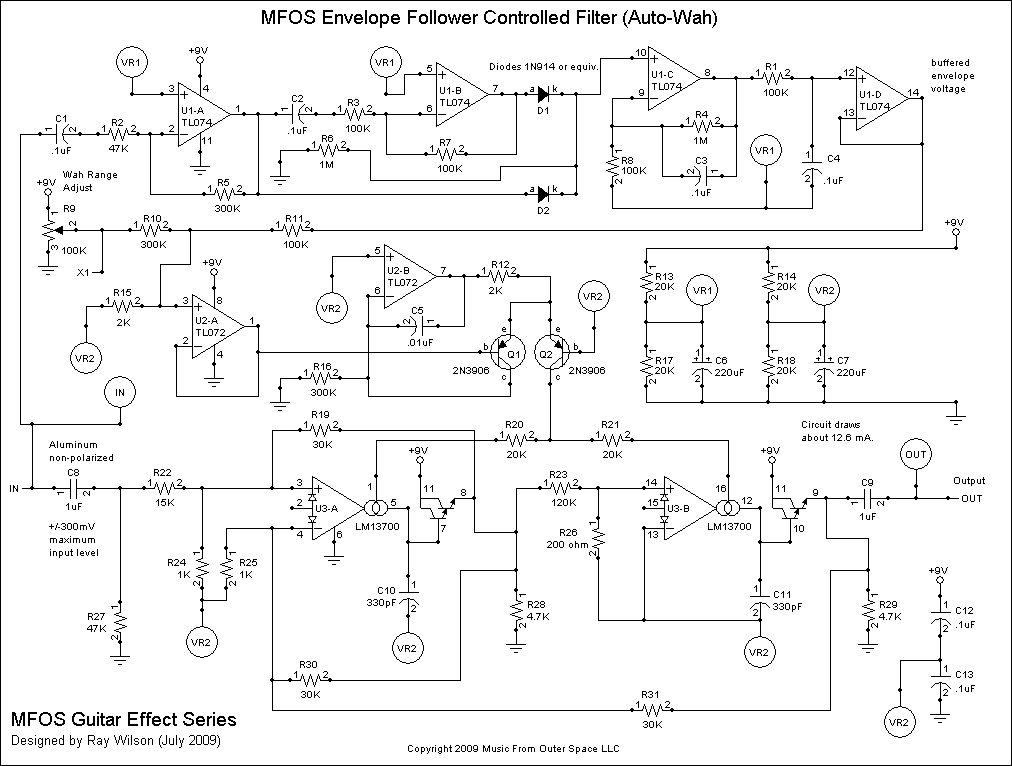
Schematic Page 1
The op-amps used in this circuit take + and - voltage to operate correctly. In order to fake them out since we are only using a single 9V battery we create a virtual ground point that is at 1/2 the supply voltage. By having one virtual ground for the filter section and one for the envelope detection section we keep the guitar signal path as clean as possible. After all it's only 2 resistors and 1 electrolytic cap for each virtual ground. A small price to pay for a clean signal path. R13 (20K) to 9V, R17 (20K) to GND, and C6 (220uF electrolytic) between the junction of the two resistors and GND accomplish what we need. C6 charges to 1/2 the supply and then provides a relatively low impedance source for the virtual ground point. There is relatively low current consumption (12.6 mA) in this circuit so the op-amps think they are seeing a supply of +4.5V, -4.5V and GND. They work fine at this voltage and actually well into the battery's discharge curve. A conservative estimate for a 500 mAH alkaline cell is about 40 hours of operation. Unplug the guitar's jack from the effect to avoid discharging the batteries unnecessarily.
The guitar's signal takes two paths in this circuit. One is through the envelope detector and one is through the low pass filter. We will first consider the envelope detector portion. Circuit point "IN" is AC coupled through C1 (.1uF ceramic cap) into the inverting amplifier U1-A. The gain of this inverting amp is about 6.3 (300K / 47K). The non-inverting input of U1-A is connected to the virtual ground point VR1 (voltage reference 1). This causes the output of the op-amp to be at a DC level of 1/2 supply (4.5V with a 9V battery). The output goes to the anode of D2 whose cathode is tied to both the non-inverting input of U1-C and one end of resistor R6 (1M) whose other end goes to ground. Remember ground is the negative side of the pseudo-bipolar supply. The output of U1-A also goes to AC coupling cap C2 (.1uF ceramic) and on to U1-B unity gain inverting buffer. The non-inverting input of U1-B is connected to the virtual ground point VR1. U1-B's output is connected to the anode of D1 whose cathode is tied to both the non-inverting input of U1-C and one end of resistor R6 (1M) whose other end goes to ground. The DC level at U1-C's non-inverting input is about 1/2 supply minus one diode drop (or about +3.9V in reference to VR1). U1-A in conjunction with U1-B and associated components comprise a full wave rectifier for the input signal. The positive excursions of the output of U1-A go through D2 and are dropped on R6. The negative excursions of the output of U1-A are inverted by U1-B and associated components and are dropped on R6. If you looked at the peaks of the voltage dropped on R6 you would see the input signal's envelope. Now to get rid of the input signal's content and just leave the envelope voltage we low pass filter the voltage fed to the non-inverting input of U1-C and we level shift the output so that it starts at about -3V (in relation to VR1) and rises to a peak of about 3.5 to 4 volts (when the input signal's envelope is peaking). U1-C's output is further filtered via R1 (100K and C4 .1uF to ground). The envelope voltage is buffered by voltage follower U1-D. Thus, we have generated a nice representation of the envelope of the input signal.
We feed the buffered envelope follower voltage via R11 (100K resistor) to non-inverting voltage summer U2-A. The rest of the circuit uses voltage reference VR2 as the virtual ground. R15 (2K resistor) holds the non-inverting input of U2-A to ground. By applying the buffered envelope voltage via R11 (100K resistor) we accomplish the 50 to 1 reduction in voltage necessary to drive the exponential V to I convertor. We are not concerned with obtaining exactly 1V/octave conversion (it is not necessary here) but this scheme yields the response I wanted from the filter in response to the envelope voltage. A nice funky WAH. R9 100K "Wah Range Adjust" pot applys a variable DC level via R10 (300K resistor) to the non-inverting summer to adjust the range over which the envelope voltage controls the filter's cut-off frequency. This provides a nice level of variation so you can get various auto-wah effects.
The output of U2-A feeds the base of Q1 the control transistor of the expo convertor. Q2 mirrors the current through Q1 and applies control current to the transconductance op-amps (U3-A and U3-B). R20 and R21 (20K resistors) help to distribute the control current evenly to the two transconductance op-amps bias inputs.
The guitar signal also takes a trip through the low pass filter which is realized by the two op-amps in the LM13700 dual transconductance op-amp package and associated components. I hard wired the Q (or resonance) to get as much as I could without having the effect sit and oscillate. If you should have an issue with oscillation tweak the value of R19 (30K resistor) up a small bit at a time until all is well. The filter is based on the National Semiconductor LM13700 data sheet state variable design (LM13700/LM13700A Dual Operational Transconductance Amplifiers with Linearizing Diodes and Buffers, November 1994, FIGURE 14. Voltage Controlled State Variable Filter) and just uses the low pass output. We use another AC coupling cap for the input to isolate it from the envelope detector input. R27 stabilizes the input and without it the effect will oscillate when your guitar is not plugged in. I added 2 bypass caps out of habit more than anything else. With a 9V battery and the low current this circuit draws it is pretty clean sounding to my ears.
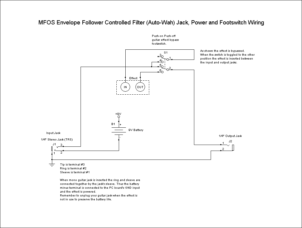
Schematic Page 2
Here we see the battery connection, foot switch wiring and jack wiring for the effect. First lets talk about how we keep the battery from discharging when the unit is not in use. DISCONNECT THE INPUT JACK FROM THE UNIT WHEN NOT IN USE. The battery's negative terminal is only connected to the circuit's ground when the input jack is plugged in. We use a stereo headphone type jack for the input jack. A stereo jack has tip, ring and sleeve connections. We use the ring and sleeve connections like a switch for the ground side of the battery. When a mono guitar jack is inserted into the stereo jack used for the input the sleeve is shorted to the ring connection. This applies the negative side of the battery to the sleeve of the jack and subsequently to the circuit's GND connection.
The output jack is a typical two conductor jack.
The bypass switch shown as a DPDT switch is actually a foot operated DPDT toggle switch. Press it once and common poles 1 and 2 connect to terminals 3 and 5 respectively. Press it again and common poles 1 and 2 connect to terminals 4 and 6 respectively. This switch is used to either insert the effect between the input and output jacks or bypass the effect completely and just feed the guitar straight from input to output jack.
The 9V battery clip's positive terminal is connected to the PC board's +9V connection point. The 9V battery clip's negative terminal is connected to the ring terminal of the stereo jack used as the input jack. The PC board's GND connection point is connected to the sleeve terminal of the stereo jack used as the input jack.
The tip terminal of the stereo jack used as the input jack is connected to the bypass switch as shown. The IN connection point on the PCB is connected to one of the common poles of the DPDT bypass switch. The tip terminal of the output jack is connected to the other common pole of the DPDT bypass switch. The OUT connection point on the PCB is connected to one of the switched legs of the half of the DPDT bypass switch whose common pole is connected to the output jack (as shown). It is important that you follow the wiring diagram closely when connecting the bypass switch.
| Approx. Current Consumption | |
| +9V | 12.6mA |
Tweaks
All guitars are not created equal. Some pickups put out a hotter signal than others. So what do you do if your guitar signal is too weak and it does not seem to drive the envelope follower enough or too hot and seems to be distorting. No problem!
Adjusting Envelope Drive
The value of R2 can be adjusted for both the signal too hot or signal too weak conditions. If your signal is too weak (does not seem to drive the wah far enough) then decrease the value of R2 which will increase the gain of the first amplifying stage in the envelope detection circuit. If your signal is too strong and you always seem to be at the maximum cut off frequency (top of the wah) then increase the value of R2 which will decrease the gain of the first amplifying stage in the envelope detection circuit.
Adjusting Signal Path Level
To increase or decrease the level of the signal going through the filter you can adjust the value of R22. Making R22 lower in value will increase the level of the signal being fed into the filter section. Making R22 higher in value will decrease the level of the signal being fed into the filter section.Adjusting Resonance
I like my pasta "al dente" and my filters ringy. You may wish for a little less ringiness (but I hope you never want squishy pasta). If you do (want less ringiness) then adjust the value of R19 up a bit (say 33K) and you will have less resonance added to the signal.Use the next available resistance value up or down when adjusting the gain so that you don't go too far. I would not suggest increasing either signal path's gain more than going lower than 10K for R22 or R2.

