Wire the front panel as shown for the production version with the following exceptions:
- There are no drivers for the sample and hold LED or the Repeat Gate generator. They were added after the prototype was evaluated. So these LEDs will not be wired up unless you add a daughter board with LED drivers yourself.
ULTIMATE Prototype Board Schematic PDFs
- Schematic Page 1 (VCO 1)
- Schematic Page 2 (VCO 2)
- Schematic Page 3 (VCO 3)
- Schematic Page 4 (Mixer)
- Schematic Page 5 (Noise)
- Schematic Page 6 (VCF)
- Schematic Page 7 (VCA)
- Schematic Page 8 (Sample and Hold)
- Schematic Page 9 (Repeat Gate)
- Schematic Page 10 (AR Generator)
- Schematic Page 11 (LFO-1)
- Schematic Page 12 (LFO-2)
- Part Placement (DESIGNATORS)
- Part Placement (VALUES)
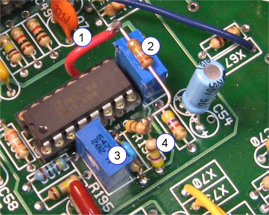
ULTIMATE Prototype Kludges
This is a change to the VCA biasing network. In place of R196 you put two 470K resistors in series (label 4). From the center junction of the two 470K resistors you connect a 180K resistor to V+ (label 2). There is a convenient source of V+ next to pin 11 of U18. I ran a short piece of wire to the 180K resistor from there (label 1). I secured the resistor with some super glue on top of R198 (trim pot). Lastly put a 100pF capacitor is parallel with R197 (label 3).