Ray Wilson authored this content while he was actively running MFOS as the founder and resident genius.
We retain the content because it reflects a valuable point of view representing that time and place.
Article by Ray Wilson
Features
IntroductionI got the bug to make a multi-segment linear envelope generator because the challenge was there. I have not seen another hardware version with more than four linear segments offered anywhere else. However that doesn't mean there isn't one out there somewhere and I know there are software versions with more segments and more control. There are a fair number of PCB to panel connections because there are fifteen knobs, one six position selector switch, ten LEDs, three switches and two jacks. I cooked this down from my initial far more complicated design. There are a fair number of quirks to this module but it will generate multi-segment linear envelopes when adjusted properly. You have to understand what is going on with the unit to get the most out of it. I highly suggest you print the schematic so you can follow along while reading the circuit descriptions if you decide to build this project. Building this project blind will lead to major frustration if you run into trouble shooting issues and don't understand the operation of the circuit.
|

|
Block Diagram
Upon being gated the envelope generator enters slope/threshold one. When segment one has completed by ramping up or down at the slope setting to its associated threshold voltage setting the counter is clocked forward and the unit advances to the next segment. This continues until all segments have executed. You may select from 2 to 7 envelope segments with the Envelope Segments selector switch. Envelope Repeat is included in the design as well as segment sustain.

Schematics
Schematic Page 1
View as PDFPage one of the schematic shows the slope and threshold voltage generation as well as the LED drivers and segment count selector switch. The ten volt zener's voltage (zener's vary slightly so the ten volts is nominal) is applied to the common I/O pin of U1 (CD4051 8 channel analog multiplexer). The binary count on the A,B and C inputs of U1 determine which set of two pots (one slope and one threshold) is energized with the Z1's voltage. When a set of pots is active they act as variable voltage dividers. The wiper of either one can be varied from zero volts to the zener's voltage (nominal 10V) by adjusting the slope or threshold pot from CCW to CW. The voltage from each active slope pot's wiper is fed via its corresponding 100K mixing resistor to the inverting input of U2-A (1/4 TL074 Quad Op Amp) pin 2. U2-A applies a gain of about .9 and permits offset to be added via R15 240K and R16 100K trim pot. Set up of the module requires that R16 be adjusted as described in the calibration procedure so that the output of U2-A pin 1 varies from approximately +4.5V to -4.5V as the knob is adjusted from fully CCW to fully CW. The integrator fed by the slope pot ramps high when the voltage fed to it is negative and ramps low when the voltage fed to it is positive. Thus positive slope will correspond to adjusting the slope knob CW and negative slope will correspond to adjusting the slope knob CCW.
The voltage from each active threshold pot's wiper is fed via its corresponding 100K mixing resistor to the inverting input of U2-B pin 6. U2-B applies a gain of about 1.8 and permits offset to be added via R45 240K and R46 100K trim pot. U2-B inverts the voltage fed from each active threshold pot's wiper and thus we must invert it again via gain of one inverter U2-D so that CW adjustment increases the threshold voltage and CCW adjustment decreases the threshold voltage. Set up of the module requires that R46 be adjusted as described in the calibration procedure so that the output of U2-D pin 14 varies from approximately -8.6V to +8.6V as the knob is adjusted from fully CCW to fully CW.
Additionally, U1 applies Z1's voltage to the resistor driving the base of each of the segment annunciator LED driver transistors (Q1 through Q8). Thus the LED that is lit will correspond to the channel currently controlling slope and threshold voltages. Resistor R12 (3K) delivers current to all of the transistor collectors but only the one that is turned on by U1 will light it's corresponding LED.
I used a dual 6 position selector switch for the segment count selector. I only show one half of the switch for simplicity as the other half is not used. When the channel selected by the switch becomes active the module resets to the "Ready" condition. Note that for two segments we reset when U1 activates I/O 3, for four segments we reset when U1 activates I/O 5, this pattern is followed except that for seven segments we never need to reset the counter driving U1's A,B and C inputs (which is U6 CD40193 by the way).
Some of the circuit points we will see again in circuit descriptions to come include:
- ZIO - Zero I/O active. Zener Z1's voltage is dropped on R117 when counter U6 is at zero.
- SCV - The adjustable voltage used to control the slope for each segment.
- THV - The adjustable voltage used to control the threshold for each segment.
- A,B, and C - The binary count corresponding to the active segment (or zero, the Ready state).
In the original design I used 3 CD4051 ICs. Two were powered with +/-5V in order to multiplex the +/-4V I was using to power the potentiometers. The third was used for LED driving and logic generation. I looked at this and said - hey wait a minute - I could be doing this with 1 CD4015 by using it to direct 10V to be delivered to each set of active pots and LED driver and then level shifting the output. TL074 U2 provides the voltage level shifting I needed so I no longer had to power the pots with +4V on one side and -4V on the other side of each pot's resistive element.

Schematic Page 2
View as PDFPage two of the schematic shows the gate conditioning circuitry, the CD40193 counter used to drive the CD4051, the current drive for the integrator, the integrator, the integrator's reset circuit, the comparator that determines when we have slewed up or down to the active channel's threshold voltage and lots of glue logic.
An external gate is fed into the module via J1 and must be at least 3V to be detected. Do not feed gate voltage higher than the supply voltage for this (or any) module or bad things will happen if it's not designed to take it. The gate signal is fed into comparator U4-C and associated components. C2 (47pF) is used to speed up the comparator's rise and fall times, R52 (100K R) and R51 (2M R) provide a bit of hysteresis, and R54 (100K R) and R55 (20K R) form a resistor divider to apply 2V to the inverting input of U4-C, setting it's threshold. When the voltage applied to the non-inverting input via R52 (100K R) exceeds the threshold voltage set by R54 and R55 and the bit of hysteresis caused by R51 then U4-C's output (pin 8) shoots very rapidly from negative saturation (about -10.5V) to positive saturation (about +10.5V).
U3-A and associated components form a push-button debouncer for S2 the Manual Gate switch. When S2 is open (not pressed) C1 charges up to +12V via R47 (100K R) and thus the output of inverter U3-A (1/6 CD40106 Hex Inverter) is normally low. When S2 is pressed C1 is discharged to ground via R49 (20K R). Once the voltage on C1 falls below the threshold of U3-A its output (pin 2) goes high. R47 and R49 in conjunction with C1 filter the switch noise a bit and U3-A which is a schmitt trigger does the rest by providing hysteresis so that we get a clean square pulse from U3-A when switch S2 is pressed and released. The voltage at the output of U3-A is also fed via D2 (1N914) to comparator U4-C's non-inverting input via R52 and thus pressing S2 is the same as applying a gate to J1.
The output of U4-C is dropped on R56 (100K R) via D4 so that only the positive excursion of U4-C is seen by the input of inverter U3-B. Allowing U3-B's input to see the low going excursion of U4-C could damage and eventually destroy gate U3-B. When U4-C is low U3-B sees ground via R56 (10K R). Thus the output of inverter U3-B is normally high and goes low when a gate is applied or S2 (Manual Gate) is pressed. When a gate is applied we reset U6 (CD40193 Four Bit Up/Down Counter) to zero very briefly and then we load count one (binary 0001) into the counter to activate the first segment's slope and threshold pots. Note that R50 (1M R) normally holds U3-C pin 5 at +12V however the low going edge that occurs at the output of U3-B when the circuit is gated pulls a shot of current through C4, bringing U3-C pin 5 low momentarily. R50 charges C4 back up again after a few micro-seconds. This causes the output of U3-C to emit a brief high going pulse which is fed via D1 to U6's "clear" pin (14), setting U6 to count 0 (ZIO becomes active). Note that R48 (1M R) normally holds U3-D pin 9 at +12V however when the pulse at the output of U3-C falls low a shot of current is pulled through C3 bringing U3-D's input low very briefly. This causes a brief high going pulse at the output of U3-D which is inverted by U3-E to be a low going pulse. This brief low going pulse is applied to the LD (Load) input of U6 which "jams" the count 1 on to the outputs of U6. Thus on the front edge of the gate signal we both reset and then load count one into counter U6.
In Gate Mode 2 we use the output of U3-B (via D26 and switch S4) to reset the counter upon release of the gate no matter what segment we are on. Circuit point X32 is where the selected output of the CD4051 U1 is fed to the counter's clear input via D5 by means of the "Envelope Segments" switch S1. Resistor R64 (100K R) holds U6's CL (Clear) input low normally but allows the pin to be driven high via diodes when it is necessary to reset the counter.
The slope control voltage is fed into the integrator's current shaper consisting of Q9 (2N3904 NPN) and Q11 (2N3906 PNP) and associated components. The SCV is fed via R57 (750K R) to the base of Q9 and via R62 (750K R) to the base of Q11. The collector of Q9 goes to +12V and the collector of Q11 goes to -12V. Thus when slope voltage is positive (slope knob < 11:00 setting) Q9 is turned on and current flows from +12V through Q9 and out the emitter where it is fed via R58 (2K R) to the non-inverting input of integrator U4-A. When current flows through Q9 the integrator slopes negative. When slope voltage is negative (slope knob > 1:00 setting) Q11 is turned on and current flows towards -12V through the transistor and thus pulls current from the integrator via R58. When current flows through Q11 the integrator slopes positive. R118 both attenuates the voltage fed to the bases of both transistors and permits the balance of the currents. The calibration procedure will detail how to balance the current. The current through either transistor is dependent on the setting of the active slope control. A wide range of current is provided by this setup which allows the integrator to ramp from minimum voltage (-8.6V) to maximum voltage (+8.6V) in as little as 2 milliseconds or as long as several minutes (a few millivolts per second).
The change to the current shaper (Q9, Q11, and associated components), from the original design, was one of the changes that saved this module from extinction. Now the slope control gives a nice adjustment for both fast and slow times. The setting of slow times is no longer crowded into a degree or two of knob travel but feels a lot more natural as the knob is adjusted from fast to slow times. Additionally the addition of the Current Balance trim allows for less drift during sustain. Changing the value of the integrator capacitor C6 from .005uF to .033 uF also made the sustain drift much less.Q10 is used to reset the integrator when ZIO is high. Q10 is off when ZIO is low and on (resetting integrator) when ZIO is high. The logic low level of ZIO (ground) causes the output of comparator U4-B to be at negative saturation which totally turns off Q10. Notice that the voltage on the inverting input of U4-B is set to about 2V. Thus when voltage on the non-inverting input is below 2V the output of U4-B is at negative saturation and when it is above 2V the output of U4-B is at positive saturation. When U4-B is at positive saturation Q10 is turned completely on. When Q10 is on it is like having a short from U4-A pin 2 to U4-A pin 1. Thus the integrator cap C6 (.033uF low leakage cap) is discharged and the output of U4-A goes to ground.
The circuit point RR (Raw Ramp) is fed to the non-inverting input of comparator U4-D (pin 12) via R70 (10K R) and THV (Threshold Voltage) is applied to the inverting input of U4-D (pin 13). As an example we will consider that segment number one's slope is set to about three o'clock (a relatively fast positive slope) and segment one's threshold voltage is set to about 5V. Recall that when a gate is applied the circuit goes to the ZIO high state briefly which resets the integrator (U4-A and associated components) by means of Q10. This causes the output of U4-A pin 1 to start ramping up or down from ground level. Immediately after the ZIO state counter U6 is preloaded with count 0001 which activates the segment one LED and activates the segment one slope and threshold controls. At that time the output of U4-A will ramp up from 0V until it exceeds the threshold voltage level on the inverting input of U4-D (5V). At that time the output of U4-D will shoot rapidly from negative saturation to positive saturation forward biasing D7 and dropping about 10.5V on R73 (4.7K R). U5-B pin 3 is normally held at +12V by resistor R72 (200K R).
Another awesome CMOS chip is the CD40193B CMOS Presettable Binary Up/Down Counter. It's a four bit counter that can count up or down and can be preloaded with a four bit binary count and then count up or down from there. It can also be reset. Its another one to keep a drawer of if you're working on anything that needs four bits of control. CD40193B TI Data SheetThe high level on the input of U5-A (pin 1) causes its output (pin 2) to go low pulling a shot of current through C11 (.001 uF C) and briefly bringing U5-B pin 3 low. This causes a brief high going pulse on the output of U5-B (pin 4). This brief high going pulse is fed via D8 to the Up Clock input of U6 which causes it to advance to count two. Now segment two's LED comes on and the slope voltage and threshold for segment two are in effect. The relationship between subsequent slope and threshold settings is very important. Since in our example the output of U4-A (point RR) has ramped up to 5V in segment one we have options for the next segment. We could ramp positive again to a voltage higher than 5V on segment two or we could decide to use a negative slope for segment two and ramp down to a voltage lower than 5V.

It is important to understand that if the slope and threshold settings do not make sense the unit will go into "slope runaway" in which the output of U4-A pin 1 will try to ramp to positive saturation or negative saturation, depending on the slope setting of the segment, which will activate the module's slope runaway response which is to reset U6 to zero. This resets the integrator taking point RR to ground. This has no ill-effect on the module and some people may find themselves using this - for lack of a better word "feature".

Slope Runaway can be confusing but by examining the series of slope and threshold voltage settings it is fairly easy to recognize and avoid. Anytime a segment is followed by another segment with the same (or inappropriately low or high) threshold voltage weird things can happen like skipped segments and slope runaway.
The module's main slope segment terminating comparator (U4-D and associated components) works slightly differently depending on whether the slope plan is made up of alternating slopes (up-down-up-down-etc.) or successive slopes (up-up-up-down-down-down-up). The following diagrams and illustrations show the operation in both cases.
Alternating Slope Operation
We will examine the alternating slope case first. After a gate occurs (Counter U6 is reset and count one is loaded) the segment 1 controls are active. For our example we will consider that the slope starts out going positive (slope knob set > 1:00) toward a positive threshold voltage (e.g. +5V).The raw ramp signal (RR) ramps up until the voltage at the output of U4-A exceeds segment one's threshold voltage setting of +5V. At that time U4-D pin 14 goes from negative saturation to positive saturation as fast as it can (< 1uS), forward biases D7 and drops about 10.5V on R73. IC U5-A pin 1 sees this as a high logic level and its output (pin 2) flies low. This causes pin 3 of U5-B to go low momentarily due to current being pulled through C11 (100pF C). R72 charges the side of C11 facing U5-B very quickly and thus a narrow positive pulse occurs at the output of U5-B (pin 4). This pulse is steered via diode D8 (1N914) to be dropped on R67 (100K R) which is connected to the UP count input of U6. The CD40193 is designed to be clocked by a positive going edge when the DN clock pin is held high. Thus the UP count pin sees a low to high transition and clocks to the next count which at this point is count 2.
The binary counter (U6) controls the multiplexer (U1) used to distribute the segment active state to the controls. Thus the segment 2 LED comes on and the slope and threshold controls for segment two become active. Remember that in the scenario being described the slope and threshold voltage settings for each succeeding segment alternate so now the slope is set negative (slope knob set < 11:00) and the threshold voltage is set to be lower than the succeeding segment's threshold voltage.
The voltage at the start of any segment is the voltage at the end of the previous segment except for segment 1 which always starts at ground.
Recall that segment 1's threshold was set to +5V thus the Raw Ramp (RR) voltage at the beginning of segment two is +5V. Segment 2's threshold voltage is lower than segment 1's (e.g. -5V) and it's slope is set negative thus the output of U4-D stays high until the output of U4-A ramps below segment 2's threshold voltage. At that time the output of U4-D shoots from positive saturation to negative saturation, reverse biasing D7 so that pin 1 of U5-A sees ground (low logic level) via R73 (4.7K R). This causes U5-A's output to go high. U5-C inverts the output of U5-A and thus goes low when U5-A goes high. This pulls a pulse of current through C12 bringing U5-D pin 9 low very briefly resulting in a narrow positive pulse at the output of U5-D. This pulse is steered via diode D9 (1N914) to be dropped on R67 (100K R) which is connected to the UP count input of U6. This drives the counter to the next segment state (3) and the segment 3 controls become active. Segment 3's slope is positive and it's threshold voltage is higher than it's predecessor (e.g. +5V). As you can see from the figure below "Operation With Alternating Slopes" this pattern continues as the comparator changes states for each segment.

Envelopes always end by means of counter U6 being reset via a positive level on U6 pin 14 (Clear) or by clocking through 7 and wrapping to 0. The Envelope Segments switch (S1) works by routing a reset signal from outputs 3,4,5,6 or 7 of U1 (CD4051 8 channel analog multiplexer) to counter U6's pin 14 (Clear input). Thus when not executing an envelope the module rests in the Ready state.
In the ready state ZIO is active and the main Raw Ramp integrator is outputting 0V (ground) because it is held reset by Q10 (2N5457). Additionally in state ZIO (Ready State) none of the pots for slope and threshold are energized thus the wipers of all of them are at 0V (ground).
This causes the output of U2-D (THV) to be the same voltage as when a pot is set completely counter-clockwise or -8.6V thus in the Ready state the output of U4-D is at positive saturation. This is because U4-D's inverting input is seeing a lower voltage (-8.6V) than the non-inverting input (0V). So when a gate occurs an initial high to low transistion of U4-D may occur and a clock may be generated however this clock is masked by the jamming of count 0001 into U6. I say may occur because if the first segment has negative slope and negative threshold voltage comparator U4-D will not go low when segment 1 starts. Instead it will go low after segment one ends.
The Envelope Repeat switch S3 when closed causes a clock pulse to be generated a few hundred uS after the module enters the ZIO (Ready) state. This clocks counter U6 into state 1 (segment 1 controls active) and the envelope continues to chase itself and repeat. When ZIO goes high C10 charges through R69 causing a couple of hundred uS delay until U5-E sees a high input. After the R69/C10 RC delay (C10 charges to ZIO level) U5-E goes low. This pulls a pulse of current through C9 bringing U5-F pin 13 low very briefly (because R68 (200K R) recharges the cap quickly). This results in a narrow positive going pulse at the output of U5-F pin 12. This pulse is steered via S3 and D10 to clock U6 up to the 1's segment active state.
Of course slope and threshold adjustments made during repeat mode change the envelope in real time and the number of segments selector can be changed in real time as well.
Part of the gate mode logic is on this page. D26 is at work when in Gate Mode 2 in which application of the gate starts the envelope and removal of the gate immediately causes a return to the Ready state.
Successive Slope Operation
When successive slopes occur clock generation gets a little more involved. Lets take a look. When the slopes of two or more segments are in the same direction it is important that their threshold voltages be successively higher (or successively lower). Caution here as asking the unit to slope up again and again (or down again and again) can lead to a Slope Runaway condition thus attention to the relationships between successive slopes and threshold voltages is important. If you're seeing weird envelope behavior look closely at the slopes and thresholds of your slope plan.A known issue is that if two successive segments have the same threshold voltage the second segment will be skipped over due to the comparator spuriously generating a glitch due to system noise which clocks U6 past the segment onto its successor. This actually makes sense when you think about it though. If you are sloping from some voltage to the same voltage it shouldn't take any time since you are already at the target voltage. However, this issue surfaces again when we discuss the sustain functionality. This behavior really is an "issue" in the sustain scenario.
While reading this you may wish to refer to the figure "Operation With Consecutive Positive or Negative Slopes". After the gate and subsequent reset and jamming of count 0001 into U6 the Raw Ramp envelope slopes up to its first threshold (e.g. +2V). Now when the Raw Ramp voltage exceeds the THV (+2V) U4-D shoots from negative saturation to positive saturation. The high level at the output of U4-D is rectified by D7 onto R73 causing the input of U5-A to see a high logic level. U5-A's output pin 2 flies low pulling current through C11 resulting in a narrow pulse at the output of U5-B pin 4. However now when the resulting pulse clocks U6 forward to segment 2 the threshold voltage goes to the higher segment two level. Since U4-D's threshold voltage is now higher than segment 1's ending ramp voltage, comparator U4-D shoots low rapidly resulting in a 4 uS wide low-high-low pulse at the output of U4-D at the segment 2 transition. When U4-D's output returns low (after 4uS) U5-A's output (pin 2) changes to the high state which rapidly recharges C11 resulting in U5-B going low.
When inverter U5-A's input (pin 1) goes low it's output (pin 2) goes high resulting in inverter U5-C's output going low. This causes a shot of current to be pulled through C12 resulting in a narrow positive pulse being emitted from the output U5-D as U5-A's output (pin 2) returns high. Diodes D8 and D9 OR the pulses from U5-B pin 4 and U5-D pin 8 into one clock pulse which is used to advance the count of U6. Diodes D8 and D9 have a very small capacitance associated with them that helps to filter the possible "crack" between the end of U5-B's pulse and the start of the output of U5-D pin 8. By steering the diodes onto R67 (100K R) the resulting clock signal is a "crack-free" blend of the two pulses.
The same clock generation sequence happens at the end of segment 2 and we step to segment 3. From segment 3 to 4 we are reversing slope direction. On my module I noted that under certain conditions the comparator can chatter as it transitions from positive slope to negative slope (segment 3 to segment 4 transistion). I only observed this after a series of positive going slopes (go figure...). This results in the pulse configuration you see in the figure. Again diodes D8 and D9 OR the logic signals resulting in a single clock pulse which clocks counter U6 to state 4.
State 4 begins the series of successive negative slopes. Again note that for successive negative slopes to work the successive threshold voltages must go progressively lower. At the start of state 4 the Raw Ramp voltage is higher than step 4's threshold voltage so U4-D's output goes high. When the Raw Ramp voltage falls to the segment 4 threshold voltage (e.g. +1V) U4-D pin 14 shoots low. The high to low transistion of the output of U4-D causes a low to high transition at the output of U5-A pin 2. The low to high transition at the output of U5-A pin 2 causes a high to low transition at the output of U5-C pin 6. This results in a short pulse being emitted from U5-D pin 8 as the falling edge of U5-C pulls a shot of current through C12. The pulse from the output of U5-D pin 8 is steered to the UP clock input of U6 via D9.
This results in U6 stepping to segment 5. Now again the ending slope voltage of step 4 is higher than the step 5 threshold voltage setting and the comparator shoots high after about 4uS. This results in a high to low transition on U5-A pin 2 which causes a pulse to be emitted by U5-B pin 4. The diodes (D8 and D9) OR all of these narrow pulses together resulting in a single low-high-low transition to clock counter U6 forward.
The transition from segment 5 to segment 6 works in the same manner as the segment 4 to 5 transition. As can be seen going from segment 6 to segment 7 reverses the slope and we see the simpler resulting clock. In my observations I did not see the same chatter during the change from negative to positive slope but if it occurred the diode ORing would quell any tendency toward spurious clocking of U6. When the segment 6 Raw Ramp voltage falls below the segment 6 threshold (e.g. -5V) The output of comparator U4-D shoots from positive saturation to negative saturation. This results in a positive going pulse being emitted from U5-D pin 8 which clocks the counter to state 7. Segment 7's threshold setting is above the ending voltage of segment 6 and so U4-D pin 14 remains at negative saturation until the segment 7 ramp voltage exceeds the segment 7 threshold voltage (e.g. +5V) at which time the output of U4-D goes rapidly from negative saturation to positive saturation resulting in a pulse being emitted by U5-B pin 4 which clocks the counter causing it to wrap around to the Ready state.
If Envelope Repeat is not on the module waits in state 0 for the next gate pulse. If Envelope Repeat is on then entry into the Ready State causes U5-E (and associated comps) to emit a clock pulse after several hundred micro seconds which clocks the counter back to the one state to start the envelope again.
Schematic Page 3
View as PDFOn schematic page 3 we see the two window comparators used for slope knob in "Sustain" position detection (U7-A, U7-B and associated components) and slope runaway detection (U8-B, U8-C and associated components). Additionally the sustain timing ramp generator and more of the Gate mode circuitry is shown.
Recall that the slope voltage at point SCV on schematic page 1 goes from +4.5V when the active segment's slope knob is fully CCW to -4.5V when it is fully CW. When the slope knob for any segment is at the halfway point (12:00 position) the Slope Control voltage at circuit point SCV when the segment is active is near 0V. The slope knob's "sustain" (12:00) position is detected by window comparator U7-A and U7-B.
The reference voltages fed to U7-A pin 3 and U7-B pin 6 are created with resistive divider R75, R80 and R84. If we consider 24V (difference between +12V and -12V) divided by 206200 (R7=100K + R84=100K + R80=6.2K) ohms we see that 116uA flows through the resistors. Thus 721 mV is dropped on R80. Since the voltage is posiive on one side and negative on one side we end up seeing +360 mV fed to pin 3 of U7-A and -360 mV fed to U7-B pin 6. Now if the SCV voltage is near 0V (> -360mV and < +360mV) the output of U7-A will be at high saturation and the output of U7-B will also be at high saturation. If the SCV is less than -360mV then the output of U7-B is low and D16 pulls the junction of R76 and D14's anode down to about 600mV (one diode drop). If the SCV is greater than +360mV then the output of U7-A is low and D13 pulls the junction of R76 and D14's anode down to about 600mV (one diode drop). In either case the input of U9-C is at a low logic level and LED9 is not illuminated.
When the Slope control voltage for the active segment is within the window (> -360mV and < +360mV) both D13 and D16 are reverse biased and R76 (10K R) can hold the junction of the the cathodes of D13, D16, D18 and D14 high forward biasing D14 and D18. In this condition current through D14 turns on Q12 and illuminates LED9 - Sustain Active LED. Current through D18 drops about 11V on R90 so that the input of inverter U9-C sees a high logic level.
Whenever the active envelope segment slope knob is in the 12:00 Sustain position the output of U9-C pin 6 is low. Note that the output of U9-C as well as point ZIO are both steered via D20 and D21 to drive comparator U8-D into positive saturation which turns on Q14 and resets integrator U7-D. Thus when NOT in a sustain segment and NOT in state ZIO Q14 is solidly on and integrator U7-D's output is held at 0V (ground).
When the EG steps to a segment whose slope knob is in the 12:00 "Sustain" position U9-C's output goes low (ZIO is already low) and Q14 is turned off allowing integrator U7-D to ramp up. When a segment is in "Sustain" mode (slope knob set to 12:00) the Threshold knob changes hats to become the "sustain time" adjustment knob. You can see that the THV is fed to the integrator's control voltage to current convertor via R103 (120K R). U7-C and U7-D and associated components comprise an expo convertor and thus we get a nice wide range of time settings. When the threhold voltage of a "Sustaining" segment is set low (more CCW) the current fed to the integrator is higher (shorter ramp times) and when set high (more CW) the current fed to the integrator is lower (shorter ramp times). Thus short sustain is toward CCW and long sustain is toward CW.
The ramp generated by U7-D rises until it exceeds the 9V threshold voltage on the inverting input of U8-A set by R106 (30K R) and R105 (91K R) and the hair of hysteresis caused by R97 (1M R). When the integrator U7-D's output voltage exceeds 9V U8-A's output pin 1 shoots from low saturation to high saturation. This forward biases D24 which drops a high logic level on R102 sending the output of U9-A low. This pulls a shot of current through C17 which causes a narrow pulse at the output of U9-B which is steered to circuit point CLK which is the UP input of counter U6. Thus the time the ramp takes to exceed the 9V threshold of U8-A is the sustain time. Sustain time can range from a couple of milliseconds to 30 seconds or more. When in the sustain mode the voltage at the output of the main envelope integrator U4-A can drift a bit. Adjusting the Current Balance trimmer (R118 1M multi-turn trimmer) can minimize the drift. This is covered in the calibration procedure.
Triggered Mode
When triggered in "Triggered" mode the envelope will sequence through all of the segments including the sustain segments and complete them all unless re-triggered in mid-envelope. If re-triggered in mid envelope the module resets and starts the envelope over again.

Gate Modes 1 and 2
Point NGT goes low when a gate is present and high when the gate is not present. When in a sustain segment and the gate is present we inhibit the end of sustain segment ramp pulse from clocking counter U6. Instead we stay in the sustain segment until the gate is released. What happens after gate release is determined by the Gate Mode selection. In Gate mode 1 we remain in the first encountered sustain section until the gate is released after which the remaining segments are executed. In Gate mode 2 we reset the unit to the Ready state when the gate is released regardless of which segment the envelope has progressed to.
When not in a sustain segment the "end of gate" clock pulse generation is disabled by the high level on U9-C pin 6 which forward biases D19 and holds pin 13 of U9-F at a high logic level suppressing the ability of U9-D pin 8 from successfully bringing U9-F pin 13 momentarily low via C14.
Quirk Alert
When in either Gate mode removing the gate signal after having entered a sustain segment clocks the counter to the next segment immediately.
Another quirk is that since the threshold knob does double duty to set the sustain time for a sustaining segment it is possible to run into the condition in which successive threshold settings can cause strange behavior. So if the threshold voltage setting (which doubles as the sustain ramp time setting) of a sustaining segment is the same as the preceding segment's threshold voltage the unit may skip over the sustain segment due to spurious clock generation caused by comparator U4-D. As the unit is clocked from one segment to a succeeding segment with the same threshold voltage setting the comparator can chatter and send you to the next state.
This is easily observable by setting a segment to sustain and then adjusting its threshold voltage (which remember is doing double duty as sustain time) until you see the sustain segment dissappear and then reappear as you adjust the threshold voltage about the preceeding segment's threshold voltage.
The Raw Ramp voltage is fed to the input of the second window comparator (U8-B and U8-C). This window comparator lets us know if the Raw Ramp voltage goes out of the -9V to +9V window. If the Raw Ramp voltage goes above 9V then U8-B's output shoots from low saturation to high saturation forward biasing D11 and dropping about 10.5V on R86. If the Raw Ramp voltage goes below -9V then U8-C's output shoots from low saturation to high saturation forward biasing D17 and dropping about 10.5V on R86. The current through either forward biased diode illuminates LED-10 via 3K resistor R83 and charges C13 (.1uF ceramic C) via R79 (3M R). When C13 charges above about 6V (set by resitor divider R87 and R88) U2-C's output shoots from low saturation to high saturation forward biasing D15 and resetting counter U6 to the Ready state. The delay caused by R79 and C13 before U2-C shoots high and resets the counter allows us to see the LED light up. Otherwise it would do so too fast to be visible.
Schematic Page 4
View as PDFPage 4 of the schematic shows the output buffer level/polarity adjustment control. By feeding the non-inverted signal to one end of R111 (100K potentiometer) and the inverted signal (U10-A is a gain of one inverter) to the other end we are able to adjust the envelope voltage from full normal output to full inverted output. The gain of 4 around non-inverting buffer U10-B is there to make up for the attenuation the signal encounters in the gain/polarity setting network. The envelope output is delivered via R113 (1K R) to the output jack J2. Synth-diyer "David" suggested the circuit for combining the level and polarity control into one knob - Thanks David.
There are a multitude of ceramic bypass caps used in the circuit and two electrolytics used to stabilize the board's power supply.
Calibration
The unit must be calibrated before it can be tested. Here is the procedure.Put on your goggles and apply power to the unit and make sure there is no smoke, flame, exploding components - the usual. Normally the module draws approximately 43mA from the positive 12V supply and 36mA from the negative -12V supply. If you see significantly more current or a chip gets hot - stop - check that all chips and polarized components are installed correctly. Backwards chip - hot hot hot and useless - replace it. Backwards polarized component - turn it around and try again. Do not proceed until the supply current looks normal.
If the unit does not respond as documented in the calibration procedure look over the board and wiring to see if you have forgotten a connection or component etc. You must trouble shoot the unit until you are able to go through the calibration steps.
Calibration of Slope Control Voltage level shifter.
- Using micro-hooks or similar IC clips connect pin 14 and pin 5 of U6 to ground.
- Press the manual gate button - this should cause segment 1 LED To light and segment 1 slope and threshold controls to become active.
- Connect a DMM set to volts to pin 1 of U2-A (Circuit point SCV).
- Adjust segment 1's Slope Control Voltage knob completely CCW.
- Adjust trimmer R16 so that the voltage at U2-A pin 1 is +4.5V.
- Adjust segment 1's Slope Control Voltage completely CW. The voltage at U2-A pin 1 will become negative and should be between -3.5V to -4.5V.
- Now iterate between segment 1's Slope Control Voltage knob fully CCW and fully CW adjusting trimmer R16 so that the voltages seen at U2-A pin 1 at both ends of the knob's travel are approximately equal in magnitude but opposite in sign. Trim until the difference in voltage magnitude at the extremes is within 20mV or so.
The interface to the module is most consistent when the slope control voltage pots are aligned with the panel so that when the knob is set at 12:00 "pointer straight up" the sustain light comes on. This is not critical and with experience with your unit you'll know the sustain position for each segment in no time (it will be - around - 12:00). However, if each knob has been aligned so that 12:00 "straight up" is the sustain position the unit's interface will seem more consistent. After finding the rotational position at which the sustain light comes on for each segment's slope pot you can loosen it's mounting nut and physically align the entire pot slightly so that it's knob points directly at 12:00. Again... not really necessary (I didn't do it on my units) and more than likely a huge bother to carry out but now you know what to do if you're a stickler for consistency in slope knob sustain position.
Calibration of Threshold Control Voltage level shifter.
- Using micro-hooks or similar IC clips connect pin 14 and pin 5 of U6 to ground.
- Press the manual gate button - this should cause segment 1 LED To light and segment 1 slope and threshold controls to become active.
- Connect a DMM set to volts to pin 14 of U2-D (Circuit point THV).
- Adjust segment 1's Threshold Voltage knob completely CCW.
- Adjust trimmer R46 so that the voltage at U2-D pin 14 is -8.6V.
- Adjust segment 1's Threshold Voltage completely CW. The voltage at U2-D pin 14 will become positive and be between +8.0V and +8.6V.
- Now iterate between segment 1's Threshold Voltage knob fully CCW and fully CW adjusting R46 so that the voltages seen at U2-D pin 14 at both ends of the knob's travel are approximately equal in magnitude but opposite in sign. Trim until the difference in voltage magnitude at the extremes is within 20mV or so.
The 10V zener you use for Z1 may not give exactly 10V and will most likely be a bit lower than 10V. In any case the zener voltage will affect the voltages at SCV and THV making them a bit higher or lower in voltage. This is not a huge problem and adjusting the trimmers so that the slope and threshold knobs deliver the same magnitude of voltage at knob extremes is the idea.
Calibration of Current Balance trimmer.
Before beginning you need to set the slope and threshold knobs as follows:
Segment 1 - Slope fully CW - Threshold V fully CW
Segment 2 - Slope fully CCW - Threshold V fully CCW
Segment 3 - Slope fully CW - Threshold V fully CW
Segment 4 - Slope fully CCW - Threshold V fully CCW
Segment 5 - Slope fully CW - Threshold V fully CW
Segment 6 - Slope fully CCW - Threshold V fully CCW
Segment 7 - Slope fully CW - Threshold V fully CW
- Set the Env Segments selector switch to position 7.
- Set the output to fully on in the positive polarity and monitor the Envelope voltage with an oscilloscope.
- Turn on the Envelope Repeat switch and press the Manual Gate button. The envelope should begin repeating.
- While observing the signal on the oscilloscope trim R118 (Current Balance) until the waveform appears to have the same slope in both the positive and the negative direction.
- Set the output to fully on in the negative polarity and monitor the Envelope voltage with an oscilloscope. The envelope should be 180 degrees out of phase with the positive polarity signal.
Envelope Repeating for Current Balance Trim

Envelope Repeating for Current Balance Trim - Detail

If the unit seems to drift a lot when in a sustain segment you can try to adjust the current balance trimmer to mitigate the drift but the procedure above sets the +/- current balance which should also mitigate drift during sustain. You will never totally eliminate sustain segment drift. It is fairly minimal but when controlling a VCO any drift is readily discernible. When controlling a VCA or VCF the drift is negligible.
Using the Unit
Setting the unit's slope and threshold controls as above in the current balance trim procedure is a good way to begin designing envelopes. Set the number of segments you want using S1 "Envelope Segments" select. Once you have the unit repeating just adjust the slopes and thresholds to form the envelope you're envisioning. If during envelope setup you encounter slope runaway then look over the controls and see where things are going off of the rails and re-adjust.When creating a slope plan with successive positive or negative slopes remember to make the threshold voltage of each successive segment a bit higher or lower (respectively) to avoid Slope Runaway.
Remember that anytime two segments have the same threshold voltage that the second of the two may be skipped over. In a way this makes sense because if you want to slope to the same threshold voltage again it should take 0 time because there is nowhere for the voltage to slope to - it is already there.
This phenomenon may be a bit more surprising when adjusting a threshold used for sustain time. If the adjusted threshold (Time) setting is the same as the preceding segment's threshold voltage you will probably skip over the sustain segment.
Experiment - Have fun.
PC Board Information
Parts Layout With Component Designators
When you are trouble shooting you'll need this view so that you can refer between the designators and the components shown in the schematic.

Parts Layout With Component Values
Print out this view to use when you are populating the PC board. Not having to continually refer between designators and the schematic will save you a lot of time.
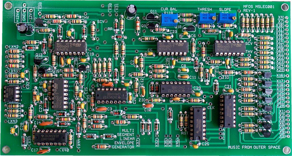
Populated PC Board
A view of the populated PC board prior to wiring. Click the image for a larger one.
Top Copper
MFOS PCB Images are as viewed from the top of the PC Board. Keep that in mind when you are using the patterns with photo or copier processing.

Bottom Copper
MFOS PCB Images are as viewed from the top of the PC Board. Keep that in mind when you are using the patterns with photo or copier processing.

Silk Screen
MFOS PCB Images are as viewed from the top of the PC Board. Keep that in mind when you are using the patterns with photo or copier processing.
Front Panel Information
Suggested 10" x 4" Inch Front Panel Layout
View as PDFThis is my 4" x 10" panel format layout. You'll have to fend for yourself regarding different plates. I'm always happy to share plate ideas from builders who complete the project. Send panel ideas to info AT musicfromouterspace.com (use @ and no spaces).
Suggested 4" x 10" Front Panel Wiring Diagram
View as PDFWiring the panel is very important and I can't emphasize enough that this is where a large majority of mistakes occur. Take your time and pay attention to every detail and you'll be glad later when the module works on first power up.

Suggested 8.75" x 3.5" Inch Front Panel Layout
View as PDFThis is my 8.75" x 3.5" panel format layout.
Suggested 8.75" x 3.5" Front Panel Wiring Diagram
View as PDFWiring the panel is very important and I can't emphasize enough that this is where a large majority of mistakes occur. Take your time and pay attention to every detail and you'll be glad later when the module works on first power up.

Seven Segment Linear Envelope Generator Project Parts List
Component Notes
All cap voltages should be 25V or more. All resistors are 1/4W 5% unless noted. You can always sub 1% resistors for any 5% resistor. MFOS PC boards use dual inline IC (DIP) packages. MFOS PC boards usually use 5mm (0.2") capacitor lead spacing unless it is obvious from the board's legend that it should be larger or smaller. I often specify axial leads for any caps mounted on the front panel but you can use radial as well by adding some wire to the leads.
Qty. Description Value Designators 3 CD40106 CMOS Hex Inverter CD40106 U3, U5, U9 1 CD40193 CMOS 4 Bit Up Down Counter CD40193 U6 1 CD4051 CMOS 8 Ch. Analog Mux/Demux CD4051 U1 1 TL072 Dual Op Amp TL072 U10 4 TL074 Quad Op Amp TL074 U2, U4, U7, U8 12 2N3904 NPN Transistor 2N3904 Q1, Q2, Q3, Q4, Q5, Q6, Q7, Q8, Q9, Q12, Q13, Q15 1 2N3906 PNP Transistor 2N3906 Q11 2 2N5457 N Channel JFET 2N5457 Q10, Q14 25 1N914 High Speed Diode 1N914 D1, D2, D3, D4, D5, D7, D8, D9, D10, D11, D12, D13, D14, D15, D16, D17, D18, D19, D20, D21, D22, D23, D24, D25, D26 1 10V Zener Diode BZX55C10 Z1 2 General Purpose Green LED LED LED1, LED9 8 General Purpose Red LED LED LED2, LED3, LED4, LED8, LED7, LED6, LED5, LED10 1 Linear Taper Potentiometer 100K R111 14 Linear Taper Potentiometer 50K R2, R4, R6, R7, R9, R13, R21, R24, R25, R27, R30, R37, R40, R43 2 Multiturn Trim Pot Vert Adjust 100K R16, R46 1 Multiturn Trim Pot Vert Adjust 1M R118 2 Resistor 1/4 Watt 1% Metal Film 100K R75, R84 2 Resistor 1/4 Watt 1% Metal Film 20K R78, R85 1 Resistor 1/4 Watt 5% 39K R59 4 Resistor 1/4 Watt 5% 3K R12, R77, R83, R101 1 Resistor 1/4 Watt 5% 3M R79 2 Resistor 1/4 Watt 5% 4.7K R73, R102 1 Resistor 1/4 Watt 5% 6.2K R80 3 Resistor 1/4 Watt 5% 30K R96, R106, R114 2 Resistor 1/4 Watt 5% 91K R11, R105 2 Resistor 1/4 Watt 5% 750K R57, R62 43 Resistor 1/4 Watt 5% 100K R3, R5, R8, R10, R14, R17, R18, R19, R20, R22, R23, R26, R28, R29, R31, R32, R33, R34, R35, R36, R38, R39, R41, R44, R47, R52, R53, R54, R64, R65, R67, R81, R87, R88, R89, R90, R93, R107, R108, R109, R110, R115, R116 7 Resistor 1/4 Watt 5% 10K R56, R63, R70, R76, R91, R100, R117 1 Resistor 1/4 Watt 5% 10M R71 3 Resistor 1/4 Watt 5% 120K R82, R103, R112 1 Resistor 1/4 Watt 5% 150K R69 1 Resistor 1/4 Watt 5% 180K R42 1 Resistor 1/4 Watt 5% 1K R113 5 Resistor 1/4 Watt 5% 1M R48, R50, R61, R95, R97 4 Resistor 1/4 Watt 5% 200K R68, R72, R74, R98 6 Resistor 1/4 Watt 5% 20K R49, R55, R66, R86, R92, R94 1 Resistor 1/4 Watt 5% 220K R45 1 Resistor 1/4 Watt 5% 240K R15 3 Resistor 1/4 Watt 5% 2K R1, R58, R104 2 Resistor 1/4 Watt 5% 2M R51, R99 2 Capacitor Electrolytic 47uF C20, C31 1 Ceramic Capacitor .001uF C10 18 Ceramic Capacitor .1uF C1, C13, C19, C21, C22, C23, C24, C25, C26, C27, C28, C29, C30, C32, C33, C34, C35, C36 5 Ceramic Capacitor 100pF C9, C11, C12, C17, C18 2 Ceramic Capacitor 330pF C3, C4 1 Ceramic Capacitor 470pF C14 5 Ceramic Capacitor 47pF C2, C5, C8, C15, C16 1 Low Leakage Film Capacitor .033uF C6 1 Dual 6 Pole Rotary Switch 2P6T S1 1 Switch DPDT (Center off) DPDT ON-OFF-ON S4 1 Switch SPST SPST S3 1 Switch SPST N.O. Push Button SPST S2 2 Jack 1/4" 2 Terminal 1/4" Jack J1, J2 16 Potentiometer Knobs Knob For all pots and rotary switch.
